Introduction
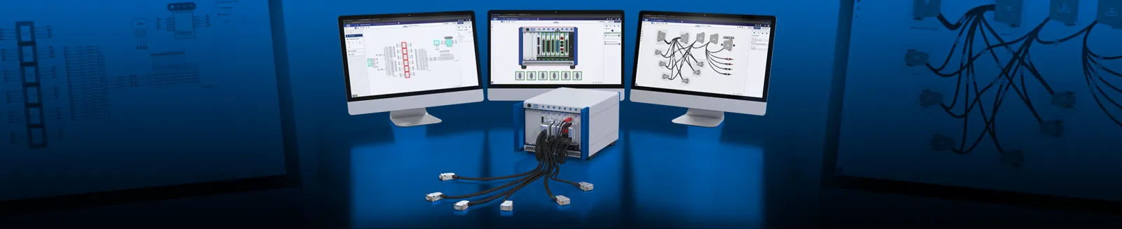
Unlock the Power of Test System Architect
Ease the Pain of Signal Path Design from Concept to Deployment
Transform your test system development with Test System Architect, our powerful online graphical toolset for intuitively designing, managing and visualizing all aspects of test system switching and signal routing, with precision and efficiency. Built on a robust database, Test System Architect’s cohesive toolset reduces errors, enables collaboration, and accelerates signal path design from concept to deployment.
Advanced Toolset for Comprehensive Signal Path Design
System Configuration Tool
Select appropriate PXI, PXIe hybrid, and LXI/USB chassis, the necessary switching, simulation, and instrumentation modules, as well as modeled Devices-Under-Test (DUTs), to align with your specific system requirements. The tool enhances your workflow by visualizing the system and enabling seamless integration with the Schematic Design Tool for automated cable creation.
Schematic Design Tool
Quickly create detailed hierarchical signal schematics for automated test systems and sub-systems, seamlessly introducing any Pickering switching, simulation and instrumentation modules. Incorporate 3rd-party instruments and Devices Under Test, graphically add all required interconnections and enable automated cable design for streamlined workflow execution.
Cable Design Tool
Automate the design of high-performance cable assemblies to exactly meet your specific needs, ensuring optimal test system reliability and signal integrity. Access comprehensive connector, backshell and wire libraries and utilize simplified connector pin-linking to accelerate the creation of any complexity of cable configurations.
Product Selector
Access the comprehensive database via specification filters, enabling you to quickly select the required products to incorporate into the Schematic Design and System Configuration Tools.
Migration Tool
Simplifies the transition from legacy test systems such as VXI and GBIB to fully-supported PXI architectures. The tool lists a comprehensive selection of obsolete products and suggests functionally compatible Pickering PXI modules.
Microwave Switch Design Tool
Configure PXI, PXIe and LXI microwave switching systems, create complex microwave signal routing and conditioning schematics, select optimal components, and simulate signal path RF characteristics to accurately predict system performance before hardware commitment.
Front Panel Design Tool
Create custom front panels for enclosures, complete with connectors, control elements, displays, mechanical parts, etc.
Enhance Collaboration and Project Management
Direct Engineering Communication
Share designs and collaborate directly with colleagues and Pickering engineers through integrated messaging and project management tools for technical guidance and design optimization.
Secure Cloud Storage
Safely store designs with version control and complete revision history tracking for project continuity and design integrity.
Documentation
Automatically create datasheets, BOMs, documentation, and images to share internally or with Pickering engineers.
Start designing your test system architecture today
Experience the efficiency of integrated test system design with Test System Architect's comprehensive toolset and expert engineering support.
Custom Cabling with the Cable Design Tool
The first step to creating a custom cable assembly is using our free online Cable Design Tool—with this tool; you can graphically design your custom cable assembly using our built-in library of standard cable sets or create them from scratch. Once completed, our engineers will generate a competitive quote for your cable requirements.
Features of our Cable Design Tool include:
- Graphical design of customized cable assemblies
- Built-in library of standard cable sets. To be used as the basis for customization, or cables can just be defined from scratch
- Add your own connectors and wires
- Allows very detailed design characteristics, including - selection of connector types, wire type, pin definitions, pin and cable labeling, cable bundling, length selection, sleeving, comments
- Export your designs to a datasheet pdf with manufacturing documentation for cable assembly. This includes product visualization, BOM, pinouts and other specifications
- Store cable assemblies in the project manager and develop them over time
- Share designs with colleagues with security level control
- Version control with complete histories and design locking
- Messages to other users and our engineers can be sent and received within the tool
We will continually update the tool to accommodate your requirements. Your data is not trapped; complete design details are always available to you at any time via the documentation or spreadsheet file.
If you get stuck creating a cable assembly or the application doesn’t allow you to draw the desired feature, submit the semi-completed assembly, and one of our experienced engineers will guide you through the process. Once the cable assembly design is finished, we will provide pricing typically within one working day. Ordering small quantities is slightly more expensive per piece, but the pricing becomes the same as standard cables when typically fifteen or more pieces are ordered.
Have questions or need more information about our custom cables or the cable design tool?
Contact Us contact_supportExamples
Cable Design Tool
Microwave Switch Design Tool
Videos
Explore our featured videos below to get started.
design_servicesDive deeper with our official YouTube channels - tutorials, demos and step-by step guides.
Pickering Interfaces Pickering Connect Pickering Electronics
Cable Design Tool introduction video
How to Design a Custom Cable using Cable Design Tool video
Demonstration of Pickering's Microwave Switch Design Tool video
Manual
Table of Contents
Test System Architect
Pickering's Test System Architect (TSA) platform is an online set of tools helping users graphically design, share, maintain and visualize various parts of test system architecture. Data reusability and mutual integration of TSA and other Pickering's software and simulation tools will increase development efficiency by reduction of redundant manual tasks and associated errors.
Key features
-
Advanced toolset for comprehensive signal path design
-
New revision of Pickering's Cable Design Tool (CDT) is a simple and efficient way of creating custom cabling solutions
-
Project Manager allows you to organize designs in a project structure, share them, track their history, keep attachments or generate various printouts.
-
Communication related utilities such as Messaging, Queries, Notes or Notification will help you to keep track with latest changes, communicate easily with colleagues or Pickering's SMEs or point out potential design issues.
-
Custom and public template library of various parts or assemblies reusable between multiple designs
Main Concepts
As Test Systems can be viewed from several perspectives the Test System Architect (TSA) has 4 main concepts how a Test System can be represented. These are:
System Configuration (SC)
The System configuration is a visual representation of the Hardware, so you see how the system looks in reality: you can observe the chassis, the modules, and a representation of the Device under Test (DUT). This is a good starting point for your first configuration. TSA uses the System Configuration Tool (SCT) for doing that.
Schema Design (SD)
The Schema design describes the modules and their connections. Simply said it is the wiring diagram of your test system. Every module is represented by its electrical symbol with connection points. The Schema Design is the most important element as from there the System Configuration and potential cable connections can be easily derived. To create a Schema TSA uses the Schema Design Tool (SDT).
Cable Design (CD)
At some point in setting up a complete Test System you need cables to interconnect everything. As we have defined the wiring in the Schema Design, we can easily obtain the needed cables from it. In TSA we can use the Cable Design Tool (CDT) to define the cables we need to connect everything.
Microwave Switch Design (MSD)
This tool lets you create a custom PXI/LXI microwave switching system. You can fit the relays, adaptors, attenuators on the front/rear panel and also inside chassis and then simulate the power loss characteristics.
Workflow in TSA
A typical workflow in creating your test system in TSA is the following one:
-
Define System configuration with the System Configuration Tool (SCT)
-
When finished, create from the System Configuration a Schema. Creating the Schema consists of the following steps:
-
Define your DUT (graphical representation, connector information, Pin-out) with the “Configurable Module” option. This is needed as the TSA does not know how your DUT looks like.
-
Define your T&M equipment (graphical representation, connector information, Pin-out) with the “Configurable Module” option. This is also needed.
-
Connect your switching architecture with DUT and T&M equipment.
-
-
A finalized Schema can then be used to create a cable in the CDT.
It is crucial to keep in mind that all components that need to be connected by a cable later have to be represented in the Schema design tool with connectors and pin-out. The Pickering modules in the TSA have these information built-in, but if you want to connect DUTs and T&M devices, you need to define that in the TSA.
warningImportant to know: Modifying data in each of these tools is not automatically synchronized with the other tools.
I.e. if you change a Schema and you already have created a cable before, the cable isn't synchronized automatically with the Schema or
vice versa.
The reason is that changes can be significant which the current version of TSA (2026) is not able to transfer.
In general the Schema is the most important piece of your Test System. From that System Configuration and Cables can be easily
obtained.
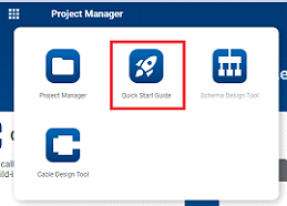
Quick Start
Quickstart guide
To speed up your project definition we developed a short wizard which navigates you through most typical project definition steps. To access wizard, navigate to Quick Navigation menu and hit Quick Start Guide icon.
Proceed with the following steps:
- Fill in project name, description and hit
Next
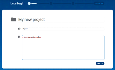
- Add any attachments relevant to project definition or put any known queries.
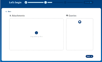
- Add as many designs as potentially required by project. You can create additional ones or delete unnecessary any time later.
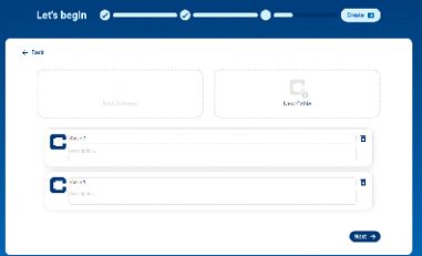
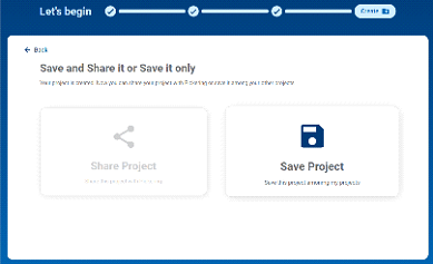
- Now Save the project. Project will appear in the project list in Project Manager with all added information
Benefit from being logged in user
You certainly can use TSA as anonymous user, draw your special cable assembly, export datafile, attach to email and send to Pickering for RFQ manually. We fully support this approach. However, being logged in user simplifies overall process and gives you access to additional functions such as:
-
Ability to save your design on server without any need for manual export/import
-
Ability to keep multiple revisions
-
Ability to share design with other coworkers
-
Ability to communicate with everyone involved via messaging or queries
-
Ability to store related attachments
-
Direct submit to Pickering for further assistance or RFQ
Quick navigation
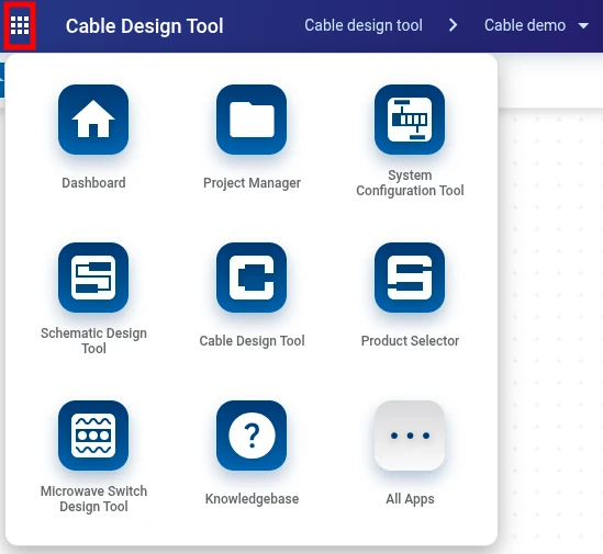
Quick Access Menu
Use the following menu to gain quick access to various TSA tools
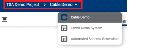
Project Navigation Menu
Use the following menu to navigate between various designs under a project.
Help
Open this menu to get page context help and link to TSA manual.
Messages
Use this menu to access project or design messaging functionality.
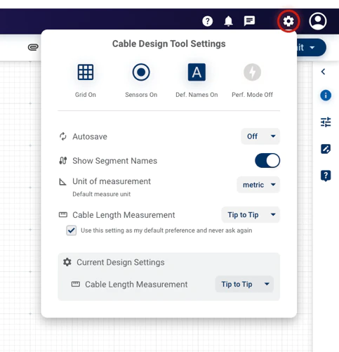
Settings
Use this menu to access various TSA settings.
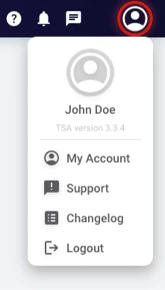
User Menu
Use this menu to access account settings, reach support, show changelog or log out of TSA.
Where to get help or further assistance
For more help, please either navigate to
Project Manager
➞
Explore apps menu➞Knowledgebase.
If you find documentation insufficient, please feel free to fill in ‘Contact Us’ form under
User
➞
Support.

How to report an issue
In case of any issue please fill in bug report form under User ➞ Support.
Common Platform Features
Feature Availability
These features are commonly available throughout the whole TSA platform.
Sharing
Sharing functionality allows multiple users to cooperate on a single project or design. Sharing functionality is available from the Project Manager page:
- Project share
- Design share
Shared user is identified by its email and one of the following roles:
- Co-owner – Same access rights as Owner. Such user can create, edit or delete designs in the scope of shared project. On design such user has access to Submit functionality.
- Customer – Same access rights as ‘Editor – can share’ and access to Submit to Pickering function.
- Editor – can share – User can edit design and share with same or less role
- Editor – can’t share – User can edit design
- Visitor – User can’t edit design but can view. User can add messages and attachments.
Shared projects will be listed in Project Manager in your personal project list but will be marked with the following icon: folder_shared
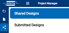
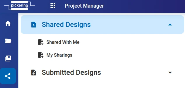
Shared designs will be listed in Project Manager under the following menu:
Please note that design access right is set by more powerful right. This means if someone shared design with Visitor role but you have access to that Project as e.g. Co-owner then Co-owner right is applied to design.
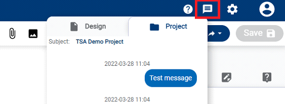
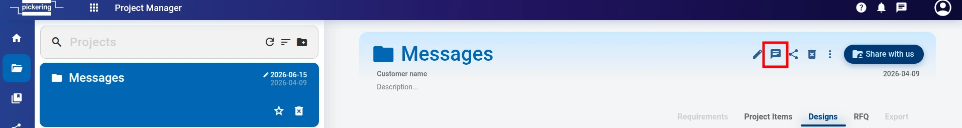
Messages
Messaging function allows users to hold communication against either project or design directly in TSA without any need for any external tools. Messages are visible to all users shared on particular design/project.
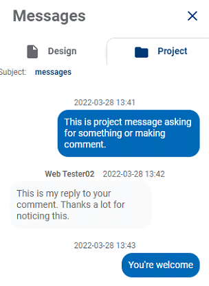
Project messages are available from Project Manager under the following menu:
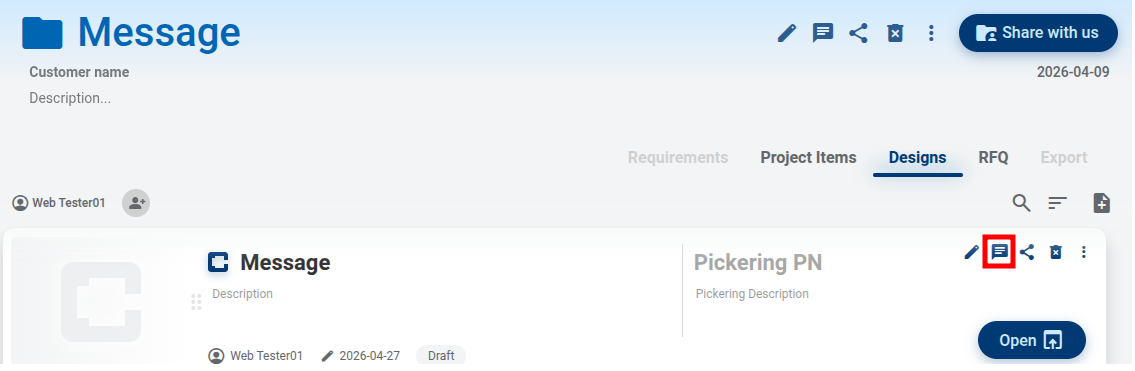
Design messages are available from Project Manager under the following menu
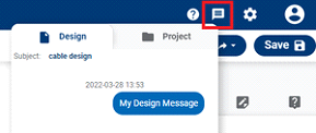
or from Design page under this menu:
Queries
Queries are very similar to messaging function however queries allow user to target question against specific project or any object on design canvas. Query can be replied by any user shared on project/design. Objects with active query are marked with icon. User can close query when resolved.
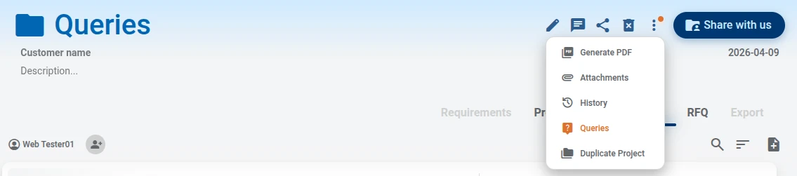
Query function on Project Manager is available under the following menu:
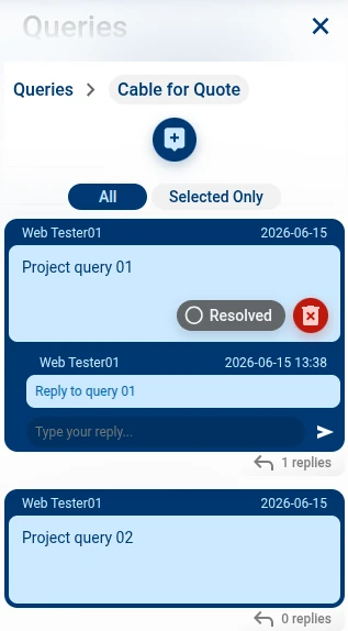
Query function on design page is available under Query tab in right hand side menu:
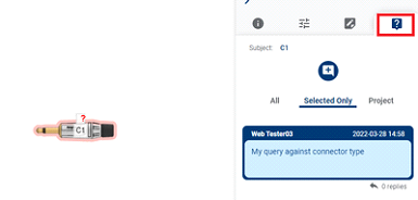
On the design page you can switch between queries related to project or queries related to design.
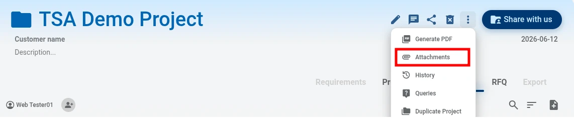
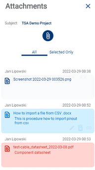
Attachments
Attachments serves as document storage for associated project or design.
Project attachments are available under the following menu:
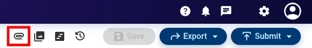
Design attachments are available under the following menu:
Each uploaded file holds information about filename, description, author and upload date. Any user having at least visitor access can read these files. File upload are limited to users having at least edit user access rights.
- Text files txt, rtf, doc, docx, odt, dop
- Table and presentation files xls, xlsx, ods, ppt, pps, pptx, ppsx
- Image Files jpg, jpeg, png, svg, gif
- Compression files zip, rar
- PDF files pdf
Export
Export function enable user to export project/design documentation or other datatypes.
Project printout is available on Project Manager and holds visualization of various designs together with their description. User has an ability to choose which designs will be included and which ones skipped. Project printout is available on Project Manager under the following menu:
Design printout is available on Design page under the following menu.
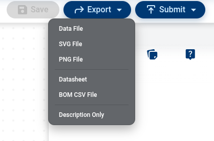
There are various printout types:
- Data File – this format enables full design export. Such datafile can be imported back to TSA system later. Typically, this is “second option” how to share designs between users or how to do design backup.
- SVG File – this exports graphics in svg format. Such file can be imported into any other graphical system supporting svg format.
- PNG File – this exports graphics in png format.
- Datasheet – in case of Cable Design Tool the pdf holds manufacturing documentation for cable assembly. This includes product visualization, BOM, pinouts and other specification.
- BOM CSV File – this exports files in csv format. Tt lists all the parts and components used in your design.
- Description only – prints only description tab.
Revisions & History
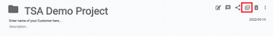
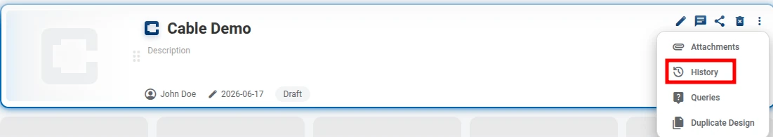
History
TSA platform tracks a lot of operations against project or design such as design creation, sharing, query or attachment creation etc. Such log can be accessed from Project Manager from the following menu:
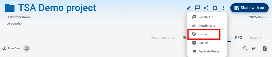
On the Design page history is available under the following menu:
Revisions
Any time during design cycle user has ability to create design revision which serves as a snapshot of design. Revision function is available under the following menu.
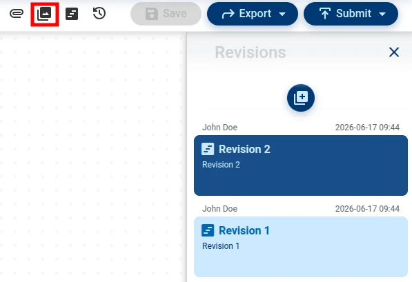
Active revision is always the last one and only this revision can be edited. Older revision can be loaded to canvas as read only. If user wants to edit older revision such changes must be saved as new revision. Older unused revisions can be deleted any time.
Concurrent access to design & Design lock functionality
Having multiple users editing a single design can bring design inconsistency or corruption. TSA platform prevents this situation with design lock function. Whenever the design is locked by other user or by the same user in a different tab design is marked with the following symbol:

And the following popup will appear:
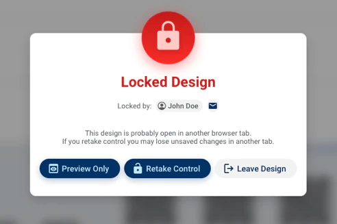
User has an option to:
- Preview Only – design will open on read-only mode
- Retake Control – other tab/user will be locked and your session will be active one
- Leave Design – window will close
Project Manager
Purpose
The main purpose of Project Manager is to organize designs in project structure. Project can be understood as a folder where multiple designs of various types are stored. Such project folder can be shared with other users. Project folder also gives access to communication, attachments, history, and other functions.
Please note each design must be assigned to a project folder. In other words, user can’t create design without project folder.
Project Manager also manage My template and Public Template design libraries. My Template is user’s own design library and Public Template is Pickering’s library available for general usage.
Project Manager also gives access to shared designs.
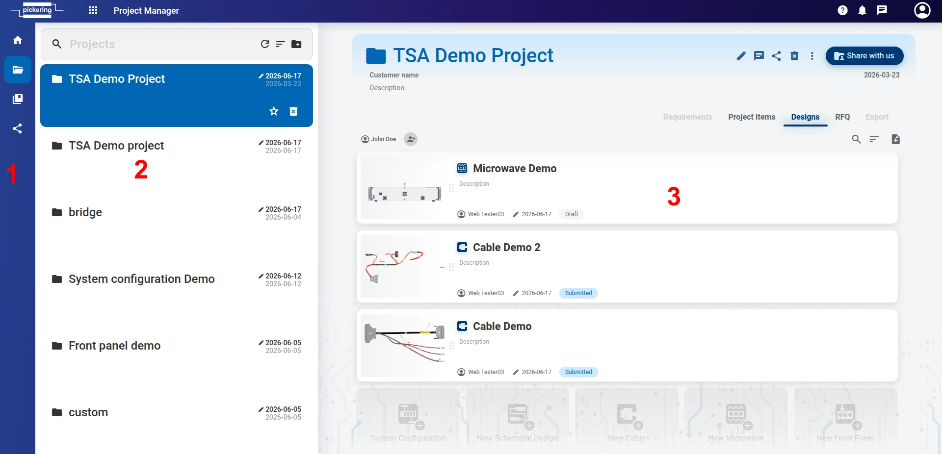
Layout
There are 3 parts:
- Main navigation between Dashboard (main overview of notifications and other important things), Projects (holding project list), Templates Library (holding custom/public templates) and Shared Designs
- Project list
- Design list
How to create project/design
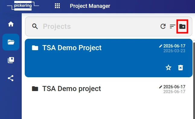
Create Project
-
To create project navigate to
Workspace
menu, hit the following button
- Then fill in ‘Project Name’, ‘Customer Name’ and ‘Project description’ and hit OK.
Create Design
-
To create new design either hit Add design button to access Add menu or use one of the shortcut panes below design list.
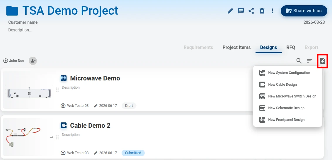
- Then fill in ‘ Design Name’ and ‘Description’ and confirm.
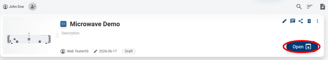
-
Open design by
Open
button:
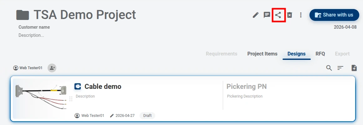
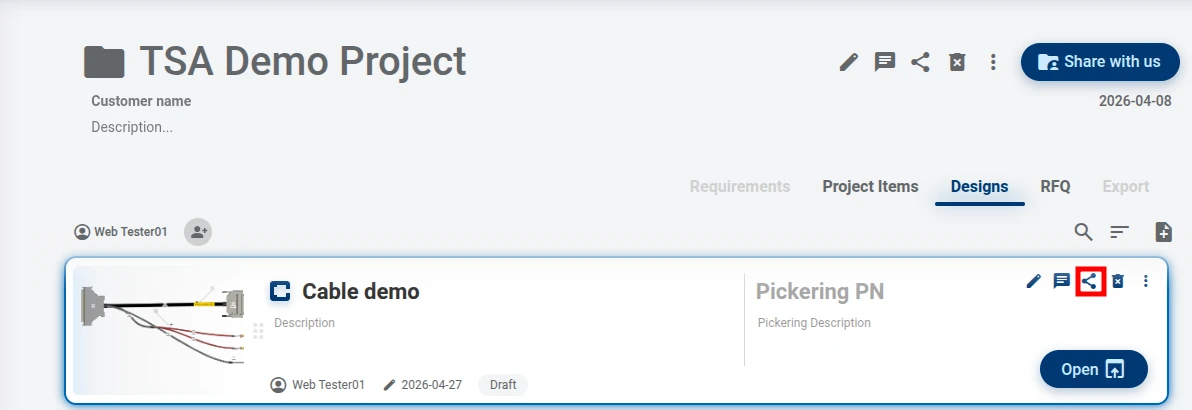
How to share project/design
-
Please refer to the following screenshot and use button 1 to share project and button 2 to share design.
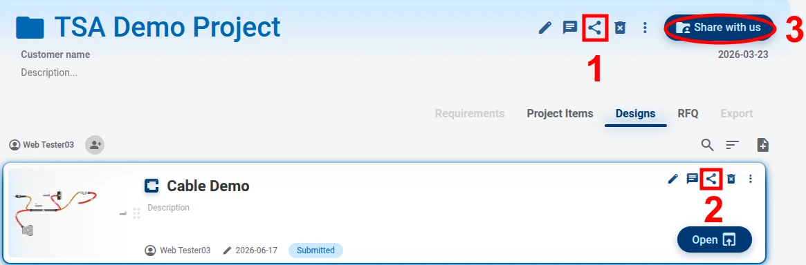
-
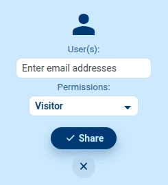
A sharing menu will open. Fill in shared user’s email and permission and hit
Share.
- User will receive notification email. Shared project will be available under Workspace menu among other user projects. Shared designs will be available under Shared Designs menu.
-
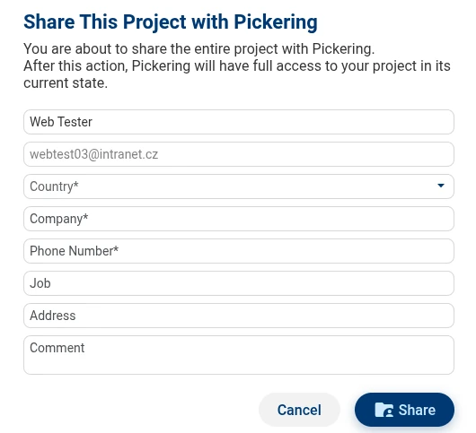
Button 3 "Share with us" allows you to share your design with Pickering. Fill in the share form and hit
Share.
Duplicate the project
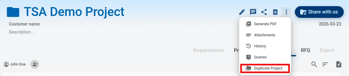
You have the option to duplicate a project. Go to Project Manager, select the project, click the Show More ... button, and choose 'Duplicate'. A notification window will pop up to let you know what will not be included in the duplicated project.
Templates Library
Under Templates Library menu you can see 2 sections. My Templates and Public Templates.
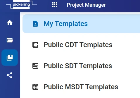
My Templates is your personal library. No other user can access this library. Such library can hold small components or even quite complex designs. Whenever user is in the situation where there is a high chance of reusability then we strongly recommend saving design or part of design as My Template. Using the menu above user can manage this library. Open and edit own templates or delete unused ones.
Public Templates is Pickering’s free library of designs.
Templates can be loaded into design via Library button. Templates itself can't be shared or submitted.
Where to find shared designs
To access shared designs please navigate to Shared designs. This will list all designs that are shared with yourself. This list will hold only designs that are shared directly, not as a part of project. Shared projects can be found under Workspace in you list of projects
Cable Design Tool
Purpose
This tool allows you to create custom cable assembly. Graphically design your cable assembly by using either our built-in library of standard cable sets or create them from scratch in the following 5 steps:
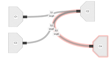
- Determine basic layout with generic connectors and paths between them
- Select connector and wire type from comprehensive libraries supplied
- Link (or autolink) connector pins at the end of each path
- Select sleeving, screening, path bundling and labels
- Save design as 'New Design'
- Submit design to Pickering
How to draw a simple cable
Video tutorial
Quick Design Workflow
-
Determine basic layout
-
Select connector and wire type
-
Link connector pins
-
Select sleeving, screening, path bundling and labels
- Save design as 'New Design'
- Submit design to Pickering
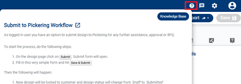
Submit to Pickering Workflow
As logged in user you have an option to submit design to Pickering for any further assistance, approval or RFQ.
Design and Manufacturing Termsopen_in_newTo start the process, do the following steps:
- On the design page click on Submit. Submit form will open.
- Fill in this very simple form and hit Save & Submit.
Then the following will happen:
- Now the design will be locked to customer and design status will change from ‘Draft’ to ‘Submitted’
- Pickering reviews the design and approves it (or possibly makes changes and sends it back as "approved with changes"). Status will change from ‘Submitted (/Waiting for Pickering)’ to ‘Approved 1/2’
- The customer will then be able to finally approve the design or make necessary changes (press Modify design) and submit changed design to Pickering again.
- Pickering and customer can repeat steps 2 and 3 multiple times, until both parties are satisfied with the design.
Please note:
- Any time Modify design is pressed, a new revision is automatically created as a safety point.
- If there is an offline agreement between Pickering and customer, Pickering SME can set design to ‘Approved Externally’ state and thus close approval process.
- If the design is in ‘Approved’, ‘Approved Externally’ or ‘Canceled’ state, the design can not be edited anymore. Now user has the ability to File ➞ Save As ➞ New Design and re-submit again.
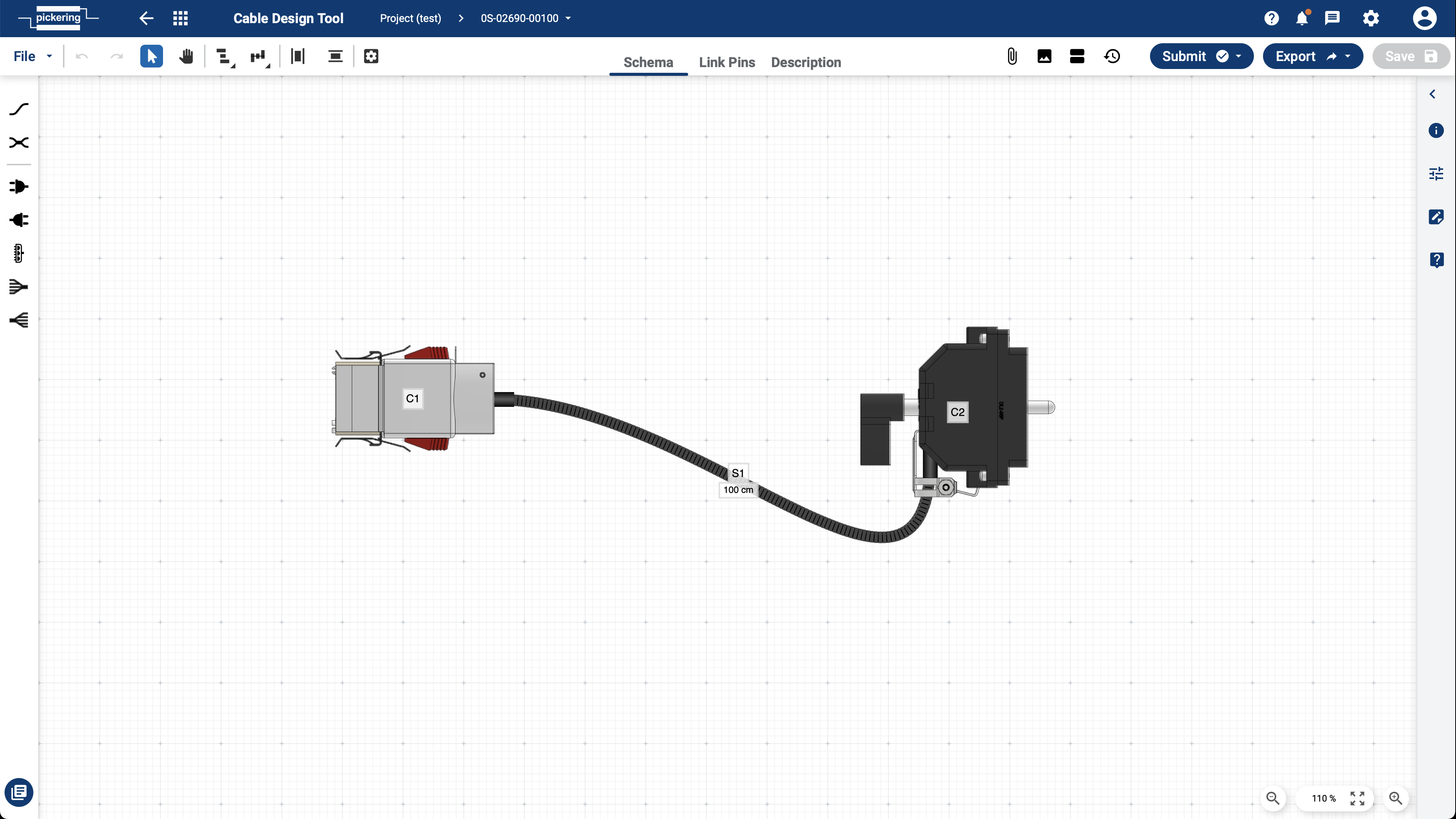
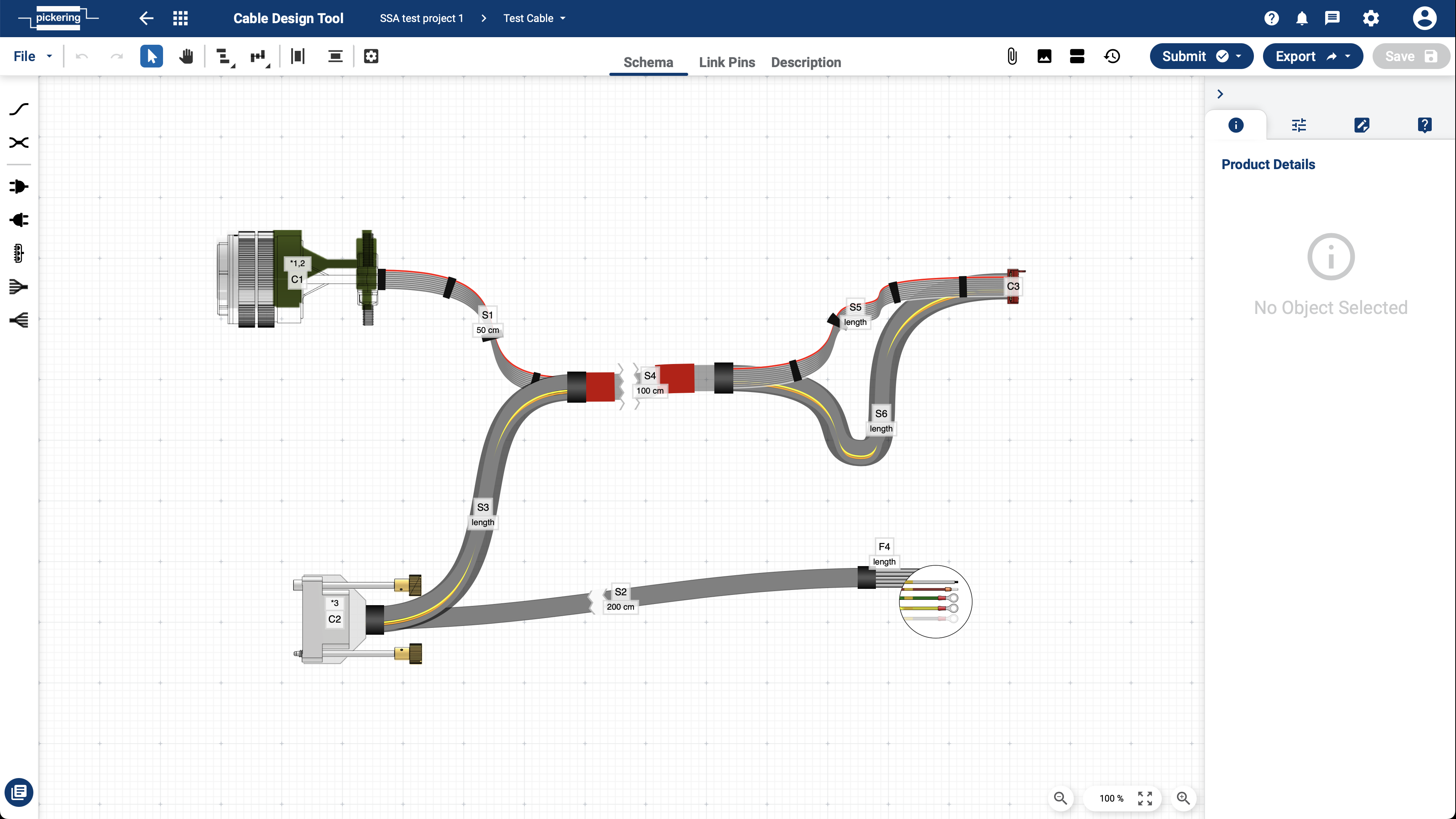
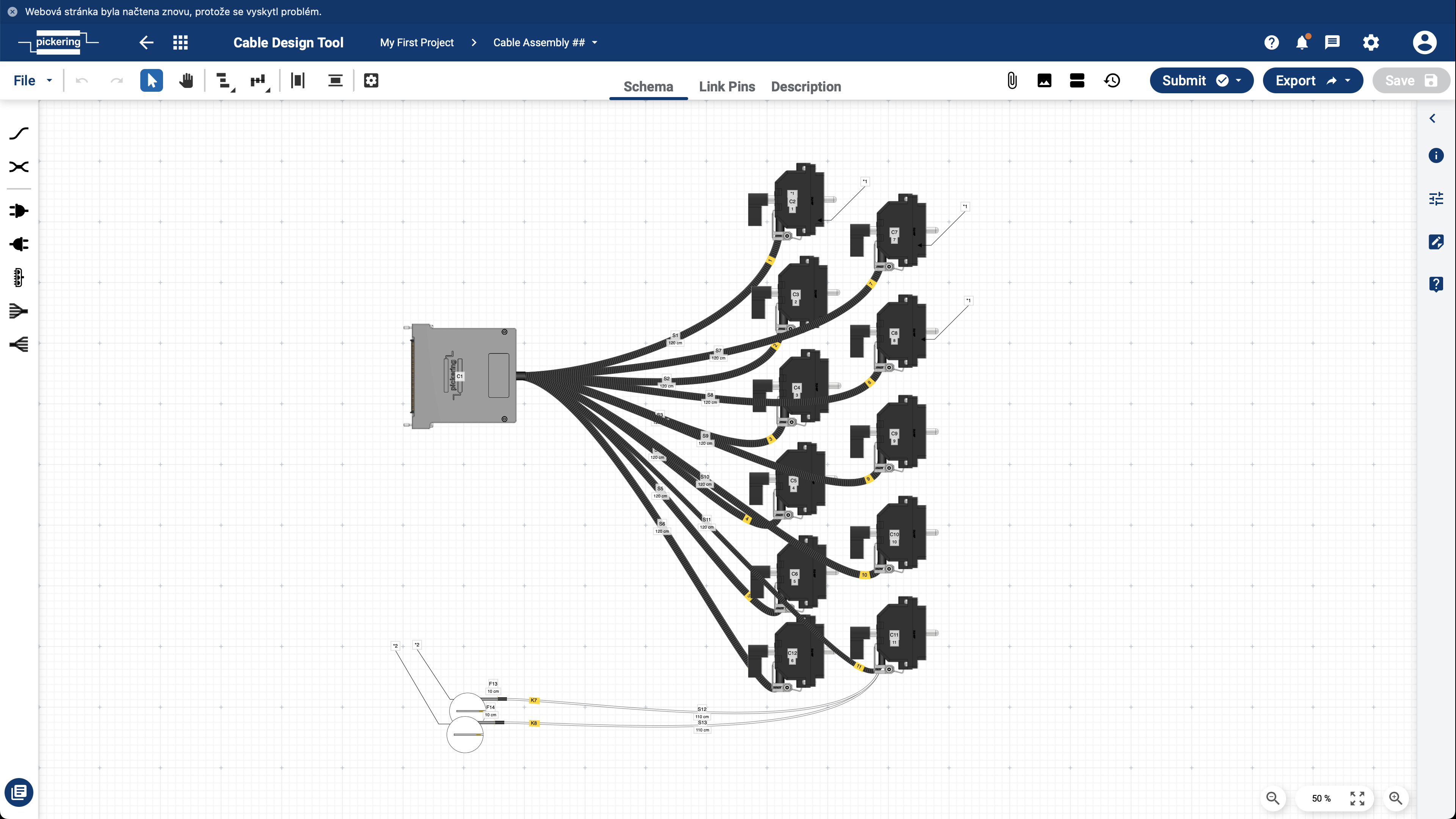
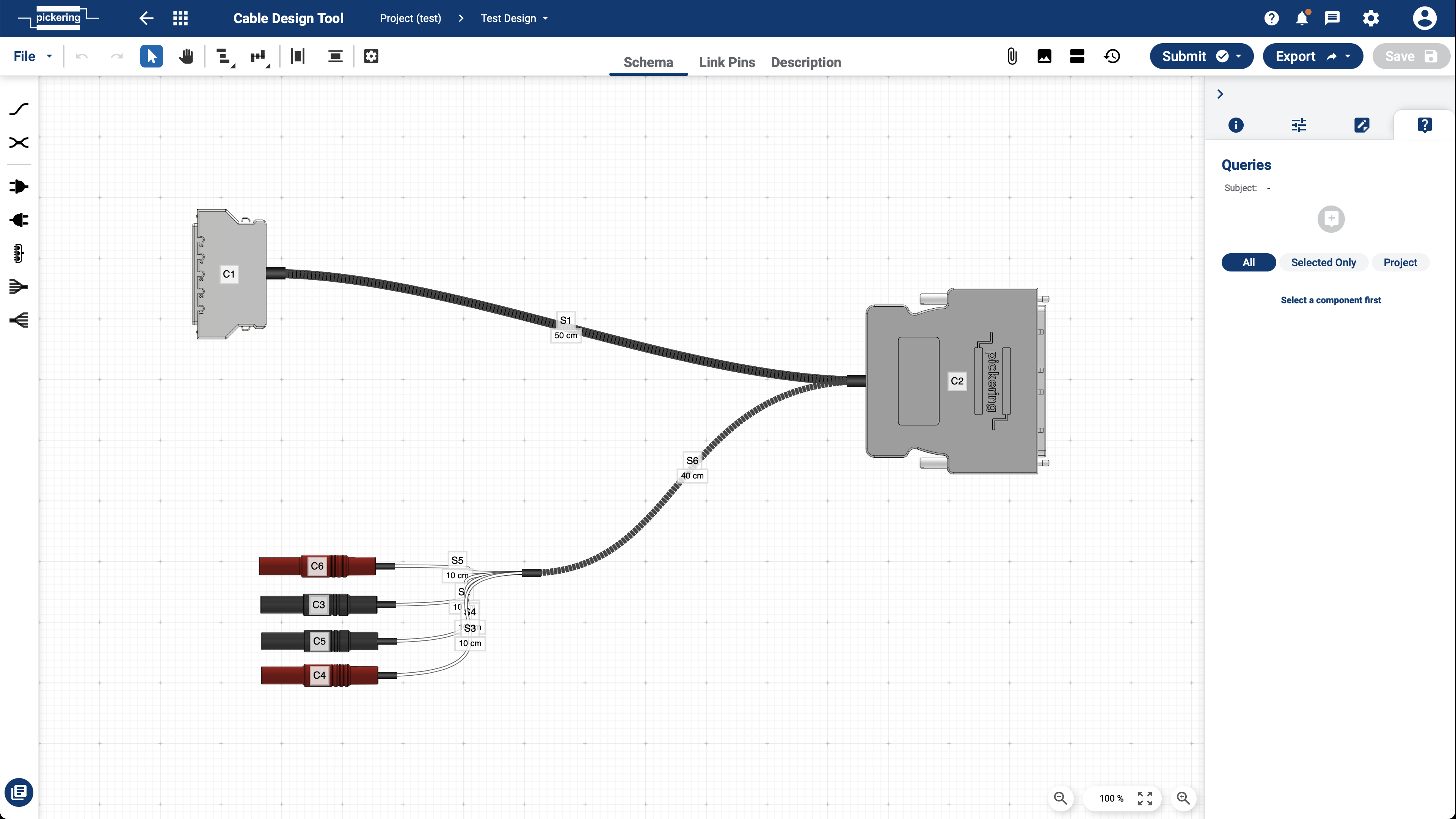
Layout
Schema, Link Pins and Description
Following screenshot denotes the key parts of Cable Design Tool layout
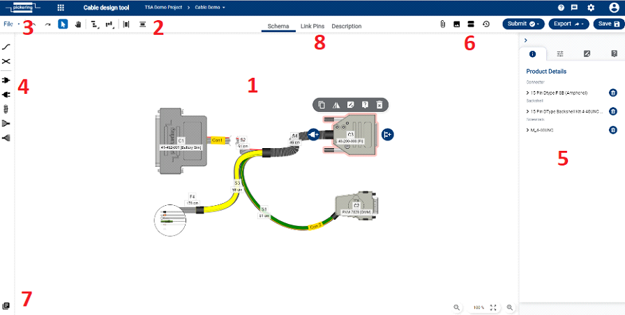
- Drawing canvas
- Tool menu – align and distribute tools, undo/redo
- File menu
- Component menu
- Right Panel – Product detail tab, Notes tab, Queries tab
- Revision, History, Snapshot, Attachments
- Library – component library, templates
- Schema, Link Pins, Description
Tool Menu
Tool menu provides functions such as object align and distribute, undo/redo and other

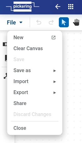
File Menu
File menu provides access to following functions:
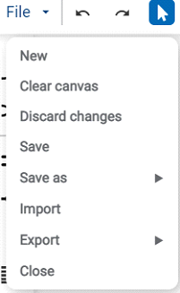
- New will create new unnamed design. User need to use Save As to save such design
- Clear canvas will delete content of drawing canvas
- Discard changes will return drawing to last saved state
- Save saves design
-
Save As
allows following options:
- New Revision – saves as a new revision to the same design. You can switch between revisions in the "Revision" section.
-
New design
– the usual saving of the design, for example, under a different name or to another project. The individual possible options
are below:
- New design into current project – this will create a copy of the design with the desired name and save it in the current project.
- New design into another project – this will create a copy of the design with the desired name and save it in the another project.
- New Project – another option is to create a brand new project and save the design into it.
- New Template – this will save your design as a template that you can load into another design via "Library" button. (note: templates themselves cannot be shared or submitted)
- Import will import previously saved/exported design datafile, typically with extension *.ssa
- Export enables to export following types: Data File, SVG file, PNG file, Datasheet, PDF description
- Close will close design page
Attachments
Attachment function is platform function allowing document storage against design. Please refer to Common Platform Features section for more details.
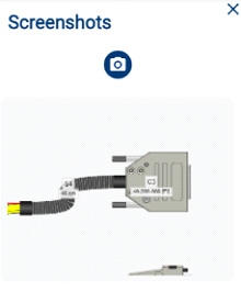
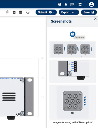
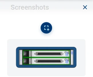
Screenshots
This function takes snapshot of highlighted area of drawing canvas. User can then either download this image or drag’n’drop onto Description page.
To activate screenshot function hit the following button

Right hand side menu will appear. Hit Photo button and highlight preferred area on drawing canvas. On mouse release snapshot will be saved and its thumbnail will appear in the list.
Revisions & History
Revision and history is platform function allowing design history and revision tracking. Please refer to Common Platform Features section for more details.
Export/Import
Export/Import function is platform function allowing exporting design in various formats and importing back into TSA. Please refer to Common Platform Features section for more details.
Messages & Queries
Messages and Queries are platform functions. Please refer to Common Platform Features section for more details.
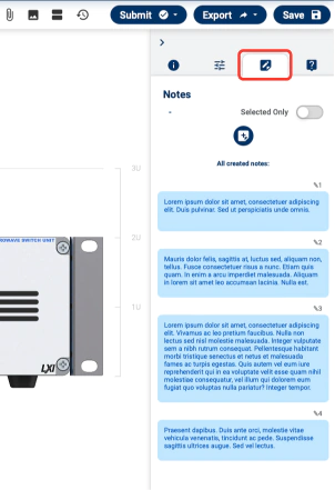
Notes
Notes function is specific to Cable Design Tool.
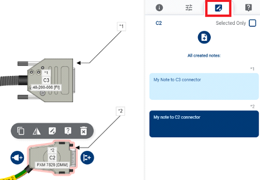
This function allows to store notes against objects in the drawing. A single note can be linked to multiple objects. Once note is resolved it can be deleted. Notes are specific to each revision which means no notes are transferred between revisions.
Schema Page
This is the main page of Cable design tool and contains drawing canvas where cable assembly is being created.
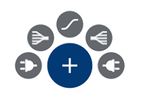
-
Start by selecting a connector component and put it onto canvas. Multiple component connect with path. See below the full library of various object types.

-
Tip & Trick: right click on canvas and get the following shortcut
-
To select connector component, click on shadow connector and hit the following button
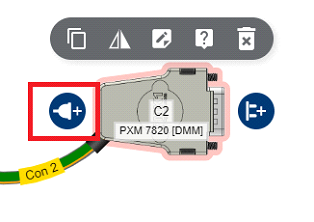
Similar button for path wire selection below
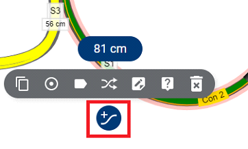
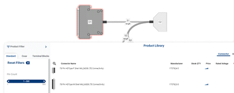
-
This will open Product Library. Use the filtering function to search suitable component
- In this way complete overall cable assembly design.
Right panel on the schema page holds information about selected products, Notes, Queries, and additional Object settings. Once all components are defined user must specify cable pinout. This is the key concept of Link Pins Page.
Link Pins Page
Link Pins Page defines how connectors are linked together by wires.
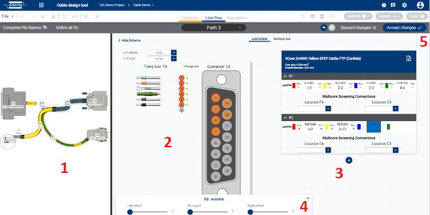
- Path selection panel
- Left and right connector display
- Pinout table
- Autolink function
- Save changes
Details about overall workflow are described in chapter How to set a pinout on the cable.
Description Page
Description page server as embedded WYSIWYG editor for notes or various design explanations. It’s usage is very similar to any other word processors. Content of the description page can be part of PDF generated on the Project Manager.
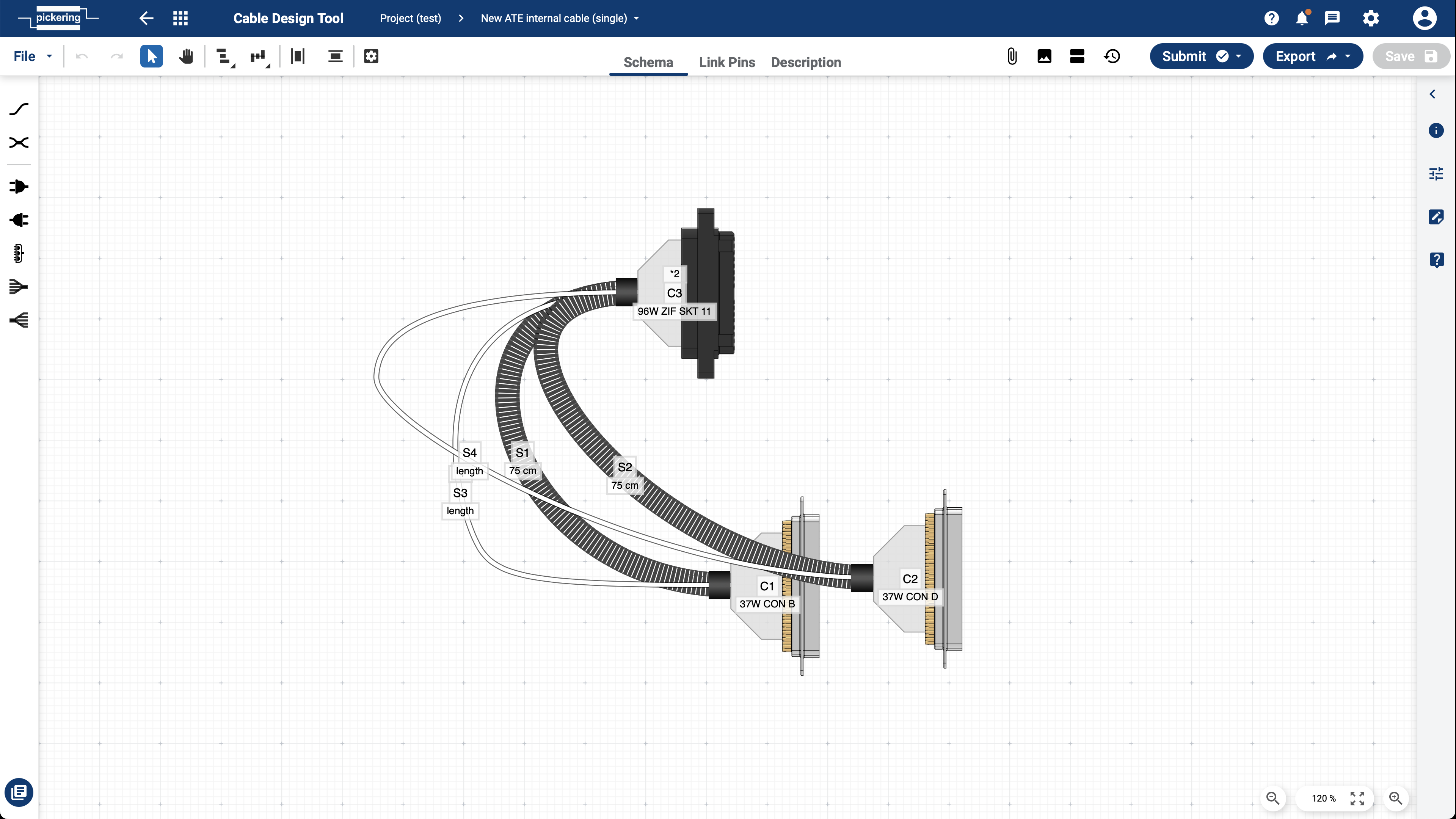
How to set a pinout on the cable
After choosing cable components like connectors, its backshells and wire types you will want to link pins.
There are several ways how to do it.
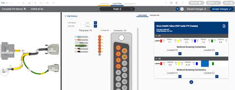
Step number one is choosing the path to be linked by left click and selecting Link Pins button
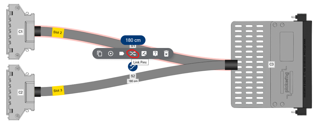
This will take you to the Link Pins screen where the pinout can be set:
-
Manually – by left click on the pins. Choosing a pin on the left side and a pin on the right side will link them together and add the link to the table on the right.
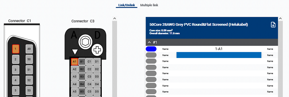
This way we can also link multiple pins from one side to opposite
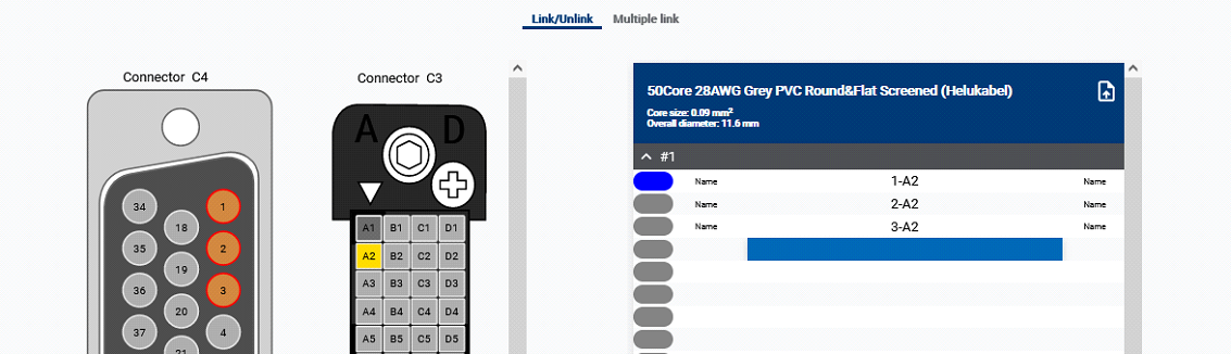
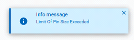
The program counts the maximum wire size for each pin, if you see an Info message on the bottom right corner saying Limit Of Pin Size Exceeded, than the pin is limited to a smaller wire or multiple wires (you will need to change the wire, or there will be no possibility to link multiple wires into the pin)
-
Autolink Function – at the bottom of the page is a linking functionality, it can be used if the pinout is more less continuous (e.g. we want to link pins 1-50 on both connectors).
By using Left / Right offset we can move the first linked pin by the number typed in.
For example we want to link 50 pins on the Connector C4 but we want to start linking from B1 on Connector C3:
We need to set number 50 (amount of linked pins) on the Pin Count bar and set the number 48 on the Right offset bar (this will move the first linked pin by 48 positions)
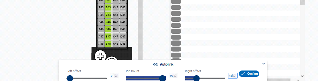
CDT will show which pins are going to be linked in green, by pressing confirm we will complete the linking. Pins are linked in a quick manner, but this only works if the pinout is straightforward.
-
CSV Import – If you have a pinout for both connectors prepared (for example in the excel sheet), you can import this by CSV Import functionality (top right corner)

How to Import pinout from the CSV file
Video tutorial
Preparing CSV files for pinout import
For CSV files it's possible to use Excel, OpenOffice or any other office editor. Generally there are four layouts of pinouts:
- not twisted
- not twisted with pin names
- twisted
- twisted with pin names
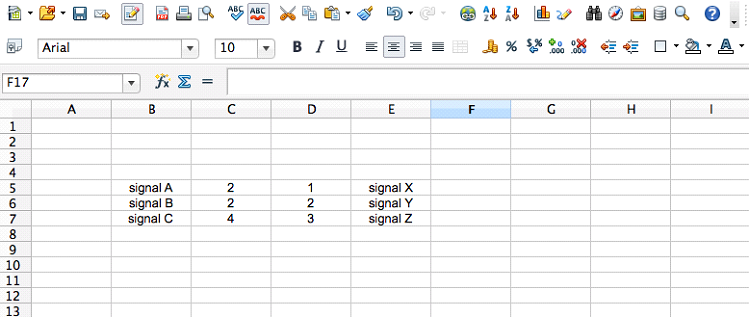
The simplest not twisted pairs should be filled in the spreadsheet in the two adjacent columns:
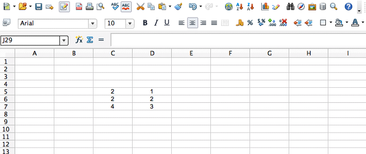
When there are pin names together with the links, they should be written on the left and right side of the links:
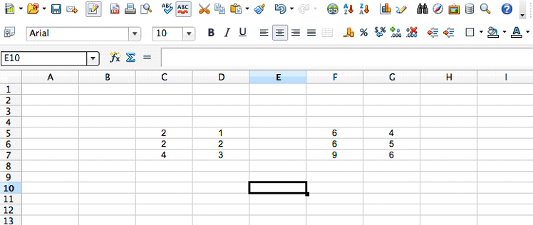
Twisted pairs contain "blocks" of data. The number of columns in a block indicates the number of twisted cores in a group. "Blocks" need to be split vertically with an empty column:
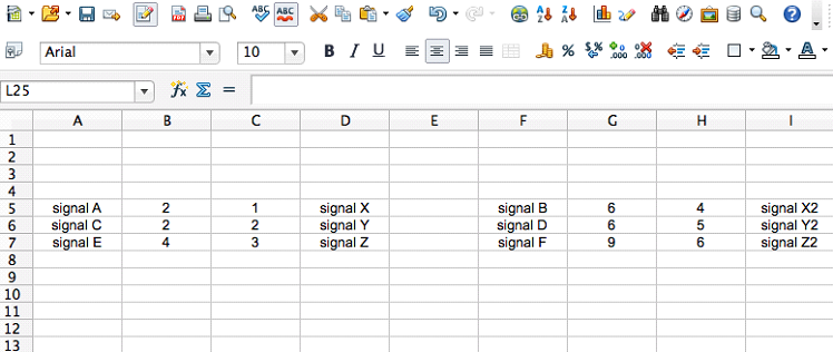
Similarly, the twisted pinout with pin names are contained within the "blocks":
Exporting and uploading the CSV pinout
Save the file from the office editor with the .csv extension.
In the linking page the wire group that is going to be linked has an import button.
Limitations for linking from the CSV file
Examples of files which will fail to import:
- Files which are not CSV
- CSV's where there are not enough wire cores for all the required links
- Numbered pins are imported into a connector which uses letters for pin identicication (or vice versa).
- Configurations where multiple wires into one pin physically doesn't fit (Area of copper is larger than the connector can take)
- Pin names are only on the left side and at the same time not on the right side - it is potentially an ambiguous situation, when there is not clear what is link and what a pin name
The detailed warnings will be displayed for each situation.
During CSV linking, if there are existing links, they will be skipped, and a warning will appear.
If the twisting (in the CSV file) does not correspond to the twisting in the wire type selected, links will be made, but the twisting information will be lost.
How to link pins by importing CSV in unterminated terminations
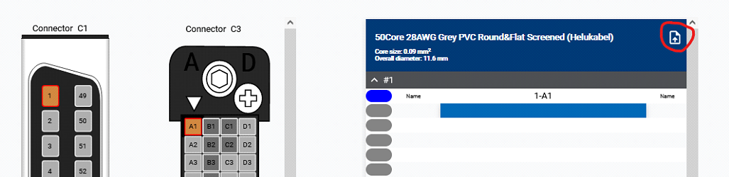
-
Choose the connector and wire type
-
Add Right (or left) flying lead (1) from the connector menu on the left vertical bar
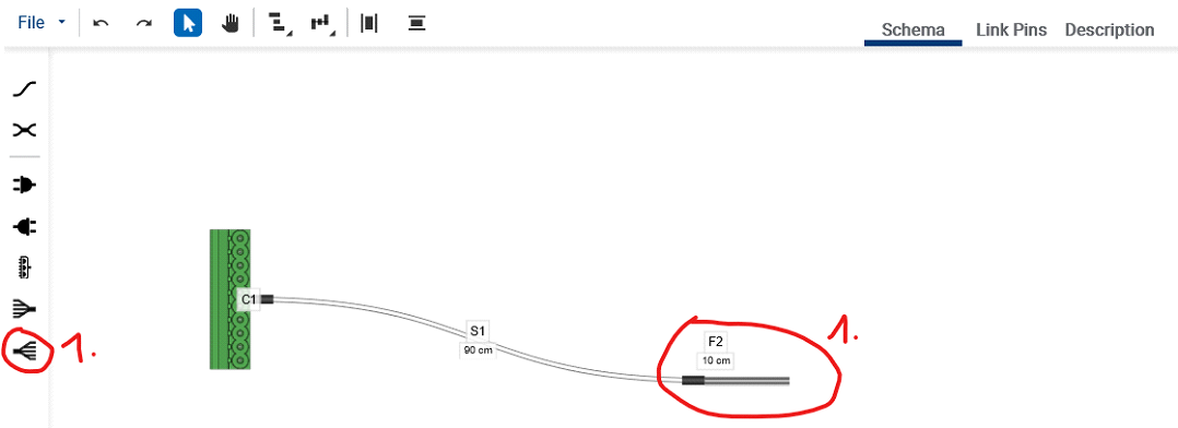
-
Prepare the CSV file, follow the markings of pin names on the connector (could be a number, sometimes the pin name also contains a letter) (2)
For the unterminated end numbers are filled in in sequence from number 1 to a number of total unterminated wires, in our case it is 10 (3)
-
Upload the file (4)
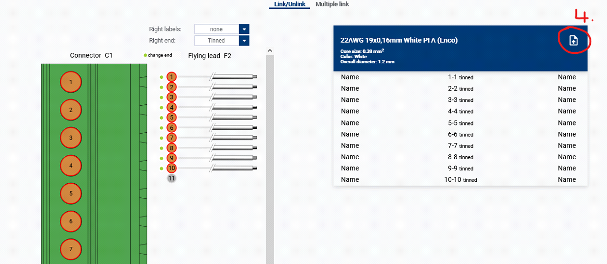
Pinout is filled in by the table.
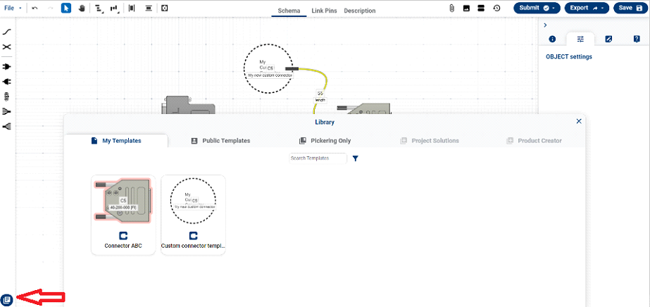
How to add a custom connector
Video tutorial
In case you need to add a connector that doesn’t exist in our database you have two options. You either can contact us with requests to add such connector or you can add one by yourself following the procedure below:
-
Add a generic connector by right click on the canvas and then either select right or left version
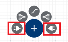
-
Highlight generic connector, go to right hand side tab ‘Product Details’ and hit the button Create custom connector…
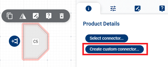
-
New page Custom Product Creator will open. Use various graphical tools to visualize your connector, edit sensors and then hit the Create product & Back button.
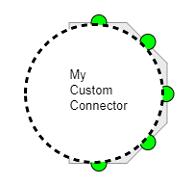
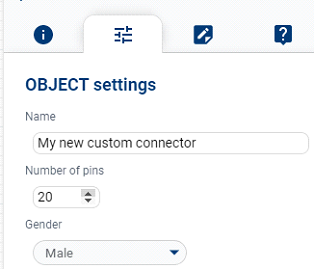
-
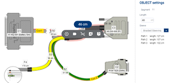
Now you can integrate such connector in your drawing. To set number of pins navigate to the right hand side menu OBJECT settings and set number of pins together with name and gender.
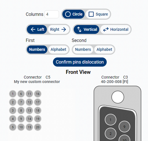
-
Once you link this connector to other connector and select wire then you can use the Link pins section. There you can change pin location for custom connector with the set of available tools on the screenshot below
-
If you wish to reuse such connector in multiple drawings we recommend to save drawing as template
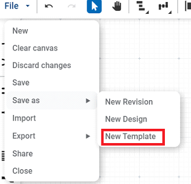
-
Then your connector will be ready to be reused in other designs:
Microwave Switch Design Tool
Purpose
This tool lets you create a custom PXI/LXI microwave switching system.
You can fit the relays, adaptors, attenuators on the front/rear panel and also inside chassis and then simulate the power loss
characteristics The following steps can help you with the design process:
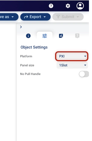
- Select chassis platform (PXI or LXI)
- Set the desired chassis bank size
- You can also choose if you want the chassis without ejection handle (LXI) or pull handle (PXI).
- Select the relays/adaptors/attenuators (schema page only) you want to add from the product list (you can also add other components such as leds, cooling vents, labels and more).
- Move the components to the desired position on the front panel.
- (optional) add Rear Panel (LXI only) and the Schema
- Once you're satisfied with your design, you can export it for other purposes or send it to Pickering for production. (don't forget to save it first)
How to design a simple microwave switching system
Quick Design Workflow
-
Select chassis platform (PXI or LXI).
You can do so in the initial pop up or in the right panel (but only at the beginning when the front panel is still empty).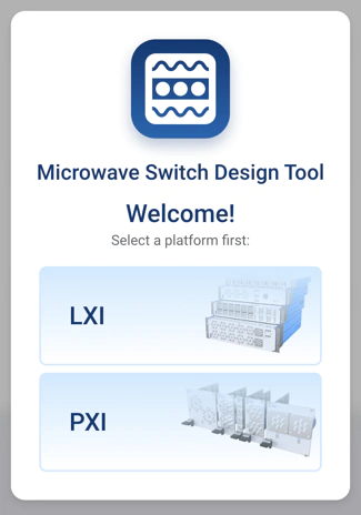
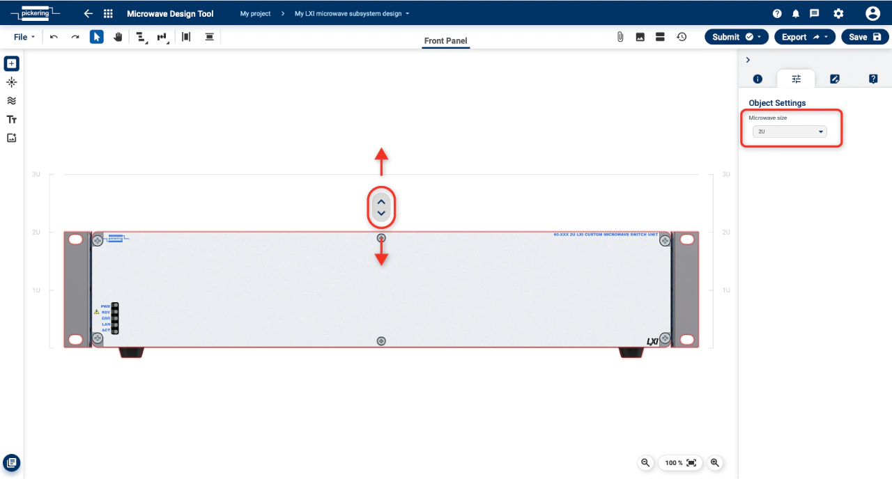
-
Set the desired chassis bank size by dragging the arrow button (above the chassis - LXI / beside the chassis - PXI) or through the
selection on the right panel.
-
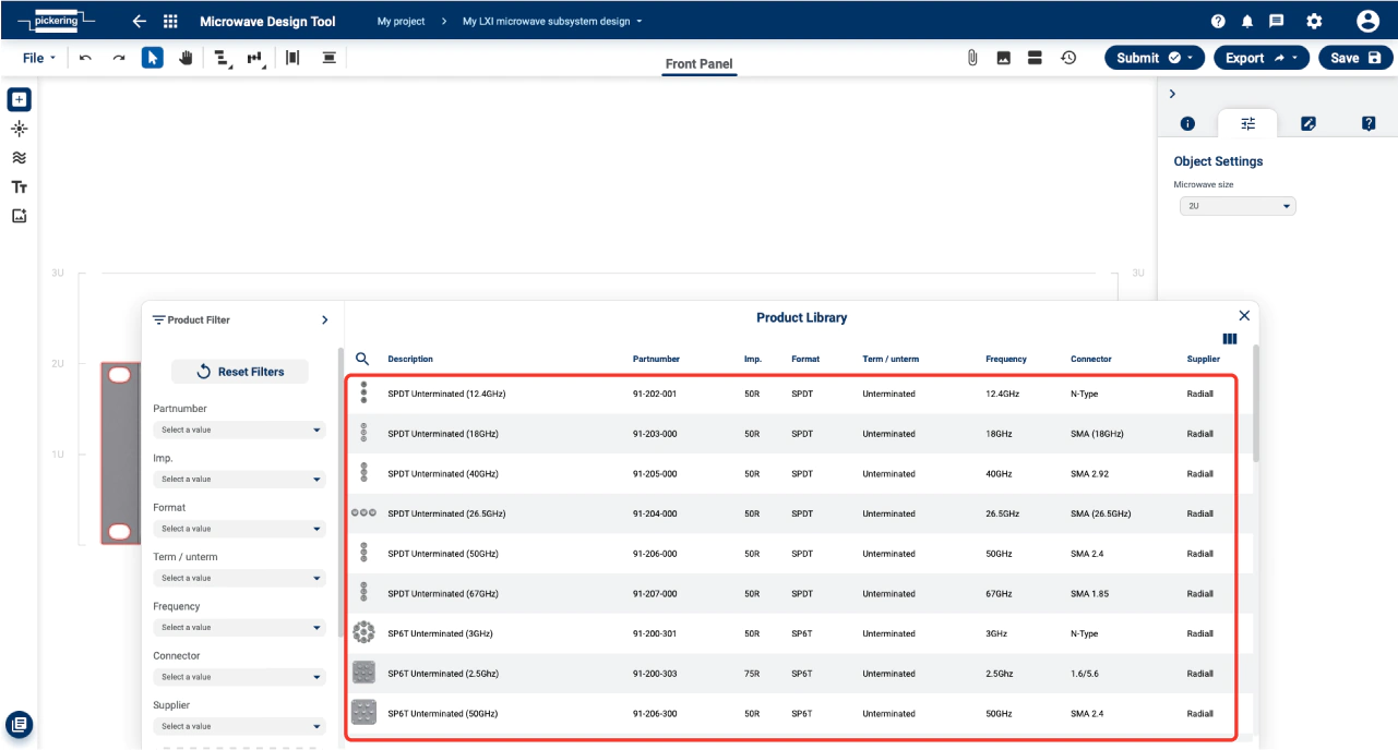
Select the relays/adaptors/attenuators
(schema page only)
you want to add from the product list
(you can also add other components such as leds, cooling vents, labels and more).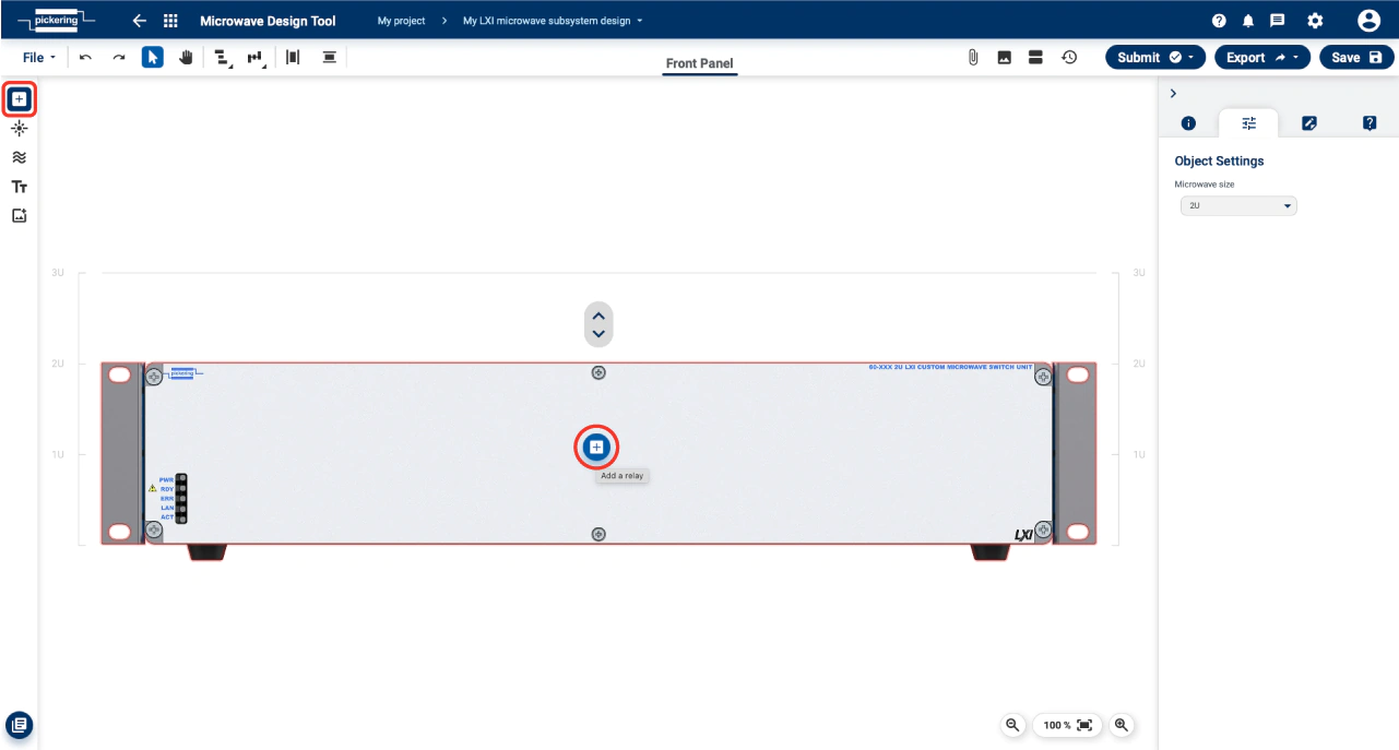
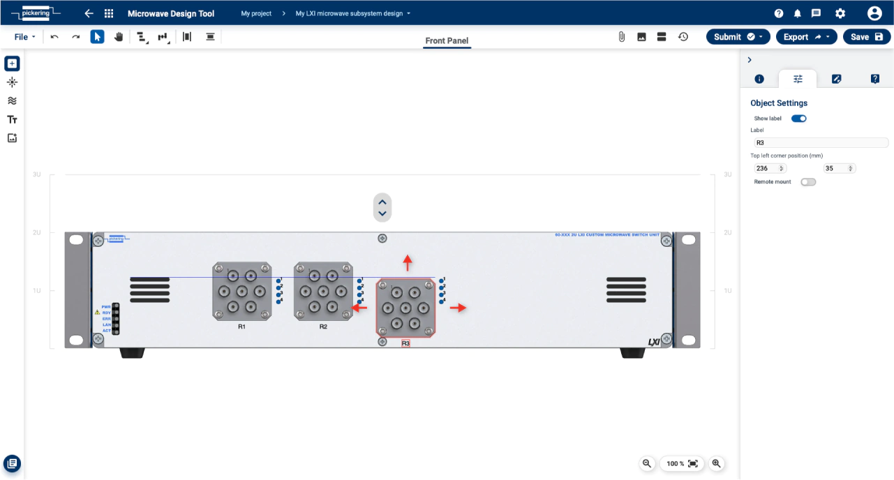
-
Move the components to the desired position on the front panel.
-
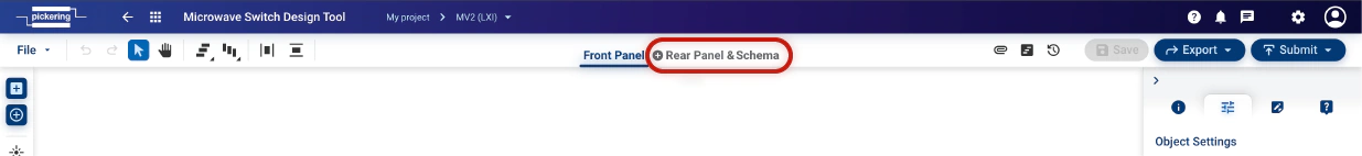
(optional) If you want, you can now add and customize the
Rear Panel (LXI only)
and the
Schema
for custom internal wiring. (those features are explained below).
-
Once you're satisfied with your design, you can export it for other purposes or send it to Pickering for production. (don't forget to
save it first)
Submit to Pickering Workflow
As logged in user you have an option to submit design to Pickering for any further assistance, approval or RFQ.
To start the process, do the following steps:
- Save the design to your project using button Save as or Save.
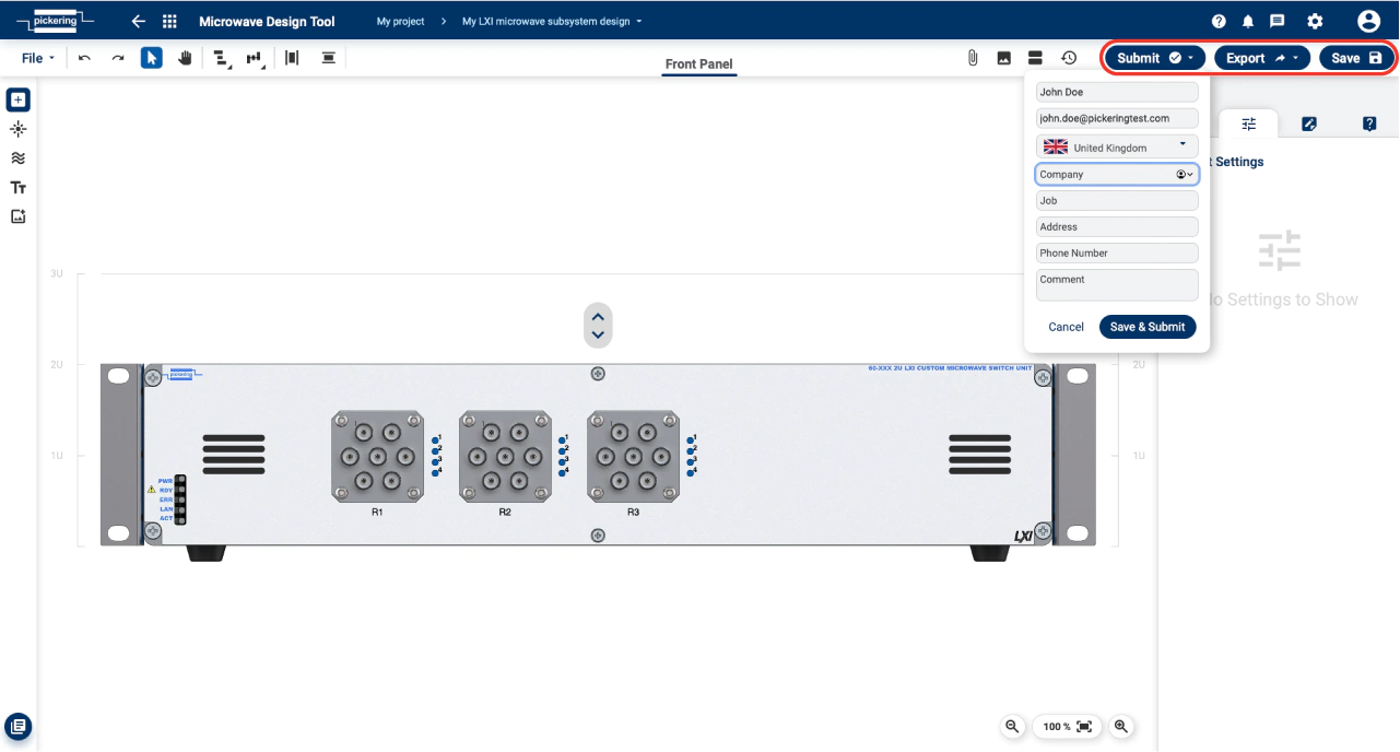
- Click on Submit. Submit form will open.
- Fill in the necessary information and then press Continue
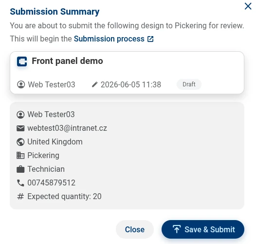
- finally, the
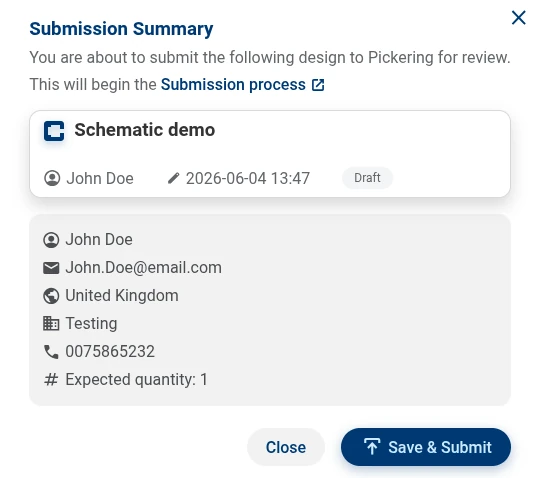
Submission Summary
window appears, where you can check the entered data one last time.
When you are sure, you can submit your design using the Save & Submit button.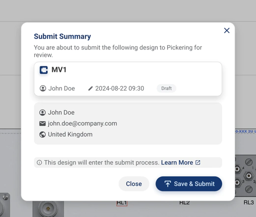
After that, the following happens:
The status of your design will change to
Submitted
and then Pickering will review your design and get back to you.
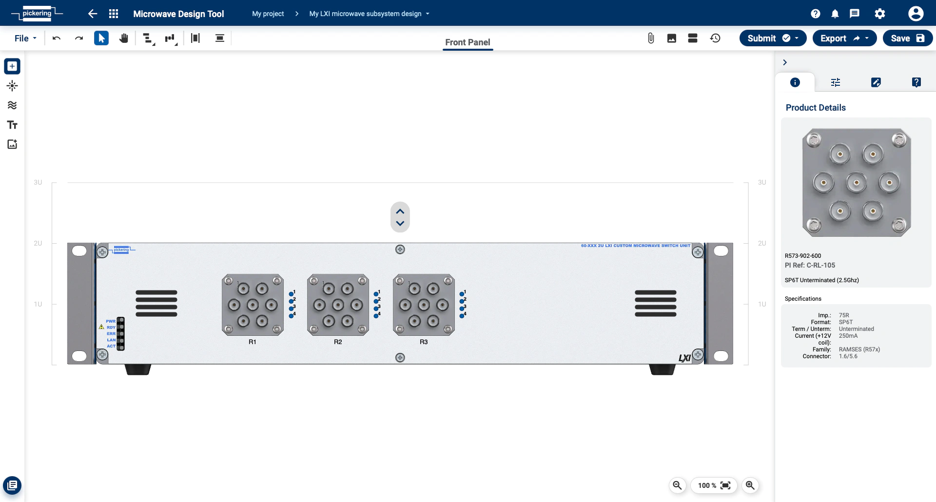
Layout
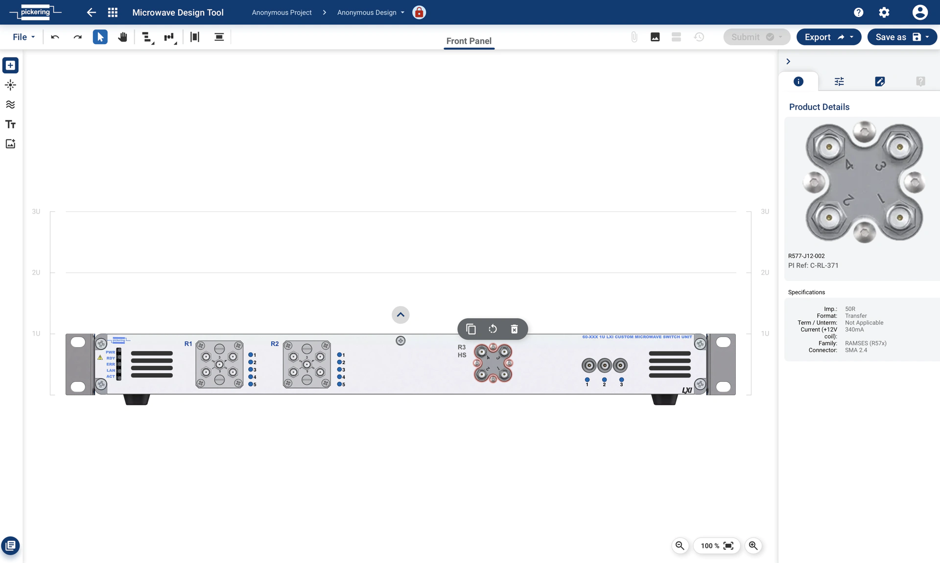
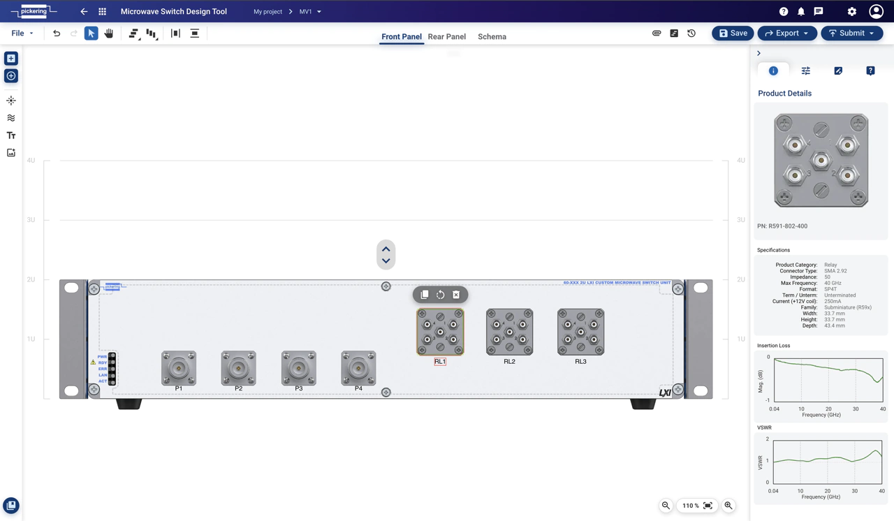
Front Panel
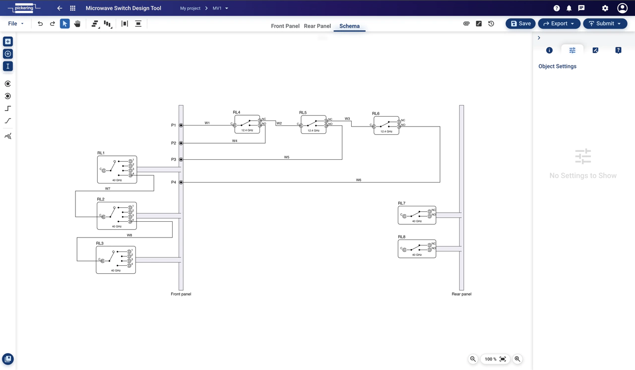
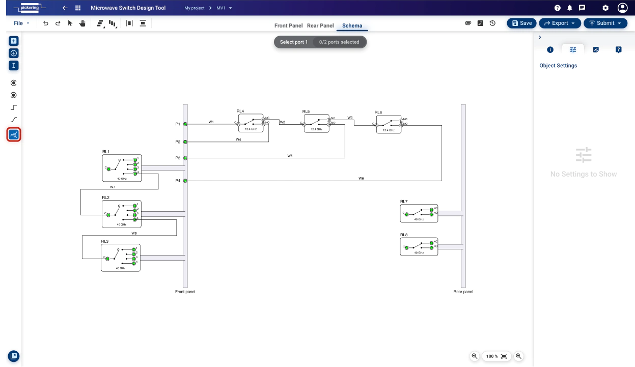
Following screenshot denotes the key parts of Microwave Switch Design Tool layout
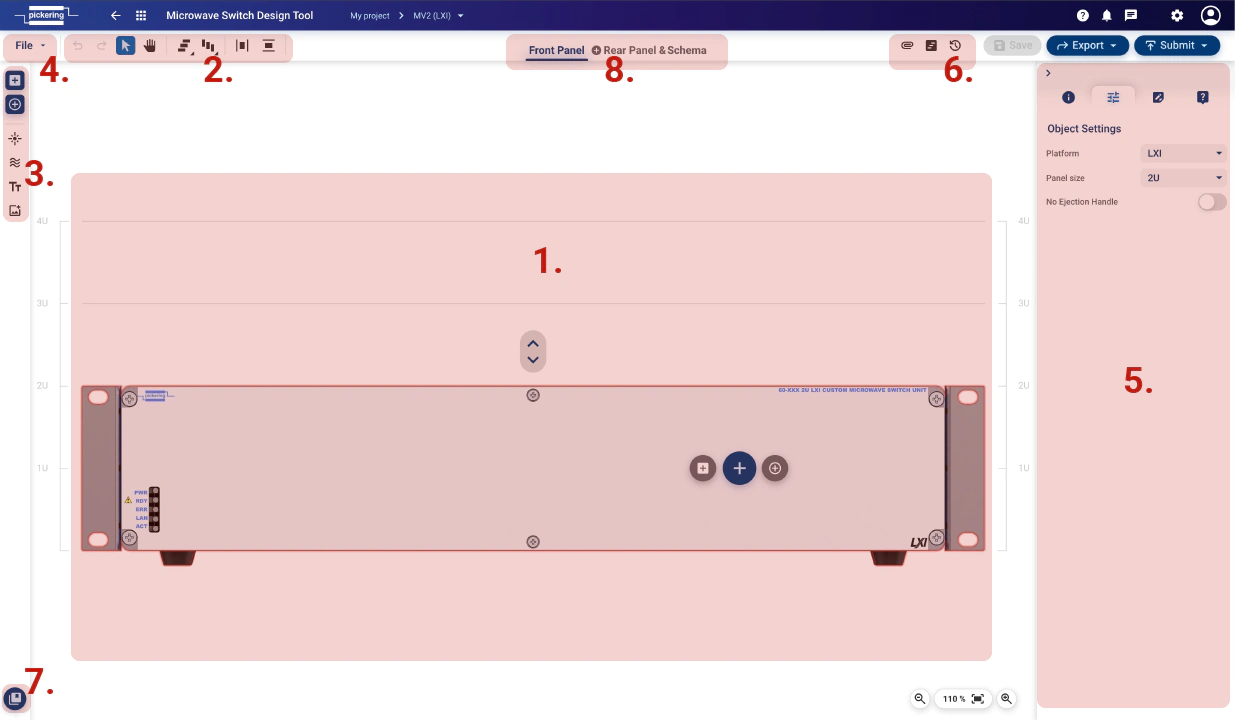
- Drawing canvas
- Tool menu – align and distribute tools, undo/redo
- Component menu – Add relay function, LEDs, Cooling vents, Text and Image
- File menu – contains essential functions to control the file/design. Such as saving, exporting, closing, etc.
- Right Panel – Product detail tab, Object setting tab, Notes tab, Queries tab
- Design menu – Attachments, Screenshots, Revision, History
- Library – here you can find templates and various library items
- Pages – you can also optionally add and customize 2 additional pages. The rear panel and schema with custom internal wiring
Tool Menu
Tool menu provides functions such as object align and distribute, undo/redo and other
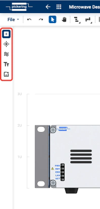
Component Menu
Through the component menu, you can add various components to the front panel of your microwave system. Such as Relays, LEDs, Cooling vents, Text and Image.
File Menu
File menu provides access to following functions:
- New will create new unnamed design. User need to use Save As to save such design
- Clear canvas will delete content of drawing canvas
- Discard changes will return drawing to last saved state
- Save saves design
-
Save As
allows following options:
- New Revision – saves as a new revision to the same design. You can switch between revisions in the "Revision" section.
-
New design
– the usual saving of the design, for example, under a different name or to another project. The individual possible options are
below.
- New design into current project – this will create a copy of the design with the desired name and save it in the current project.
- New design into another project – this will create a copy of the design with the desired name and save it in the another project.
- New Project – another option is to create a brand new project and save the design into it.
- New Template – this will save your design as a template that you can load into another design via "Library" button. (note: templates themselves cannot be shared or submitted)
- Import will import previously saved/exported design datafile, typically with extension *.ssa
- Export enables to export following types: Data File, SVG file, PNG file, Datasheet, PDF description
- Close will close design page
Attachments
Attachment function is platform function allowing document storage against design. Please refer to Common Platform Features section for more details.
Screenshots
This function takes snapshot of highlighted area of drawing canvas. User can then either download this image or drag’n’drop onto Description page.
To activate screenshot function hit the following button
Right hand side menu will appear. Hit Photo button and highlight preferred area on drawing canvas. On mouse release snapshot will be saved and its thumbnail will appear in the list.
Revisions & History
Revision and history is platform function allowing design history and revision tracking. Please refer to Common Platform Features section for more details.
Export/Import
Export/Import function is platform function allowing exporting design in various formats and importing back into TSA. Please refer to Common Platform Features section for more details.
Messages & Queries
Messages and Queries are platform functions. Please refer to Common Platform Features section for more details.
Notes
The notes feature is available on both the Cable Design Tool and the Microwave Switch Design Tool. You can add necessary design notes here.
This function allows to store notes against objects in the drawing. A single note can be linked to multiple objects. Once note is resolved it can be deleted. Notes are specific to each revision which means no notes are transferred between revisions.
Front Panel Page
This is the main page and contains drawing canvas where the front panel is being created.
Right panel on the schema page holds information about selected products, Notes, Queries, and additional Object settings.
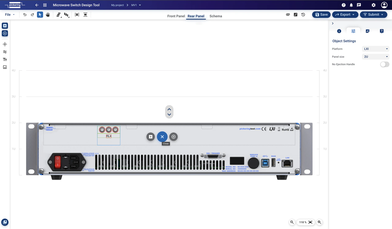
Rear Panel Page (LXI only)
This page works basically the same as the front panel page, except that it is the backside of the chassis.
You can again add various relays, adaptors, connectors or other elements here.
Just keep in mind that you have a smaller usable area.
Schema Page
On this page, you can add internal relays and attenuators in addition to relays connected to the front/rear panel.
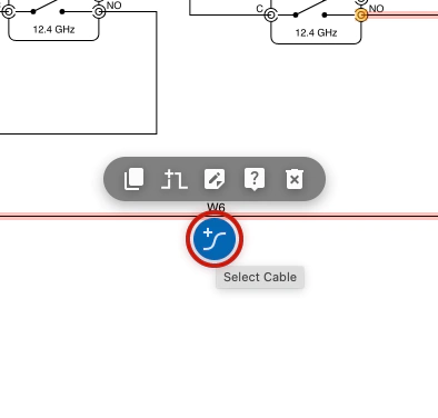
You can then connect these relays to one of the panels via a cable and connector, or you can also connect these relays to each other.
Just keep in mind that these elements must be compatible with each other (eg cable, connector, relay)
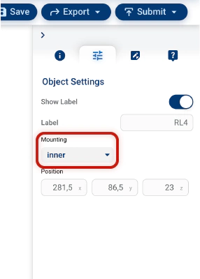
You can change the relay mounting method in the right panel in the Object Settings tab.
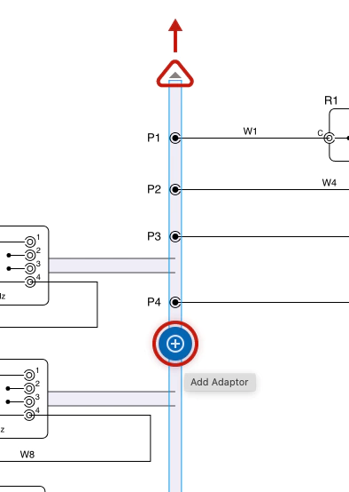
You can also simply add an
adaptor
to the front or rear panel by selecting the appropriate panel and clicking the "Add Adaptor" button
add_circle
If one of the panels becomes crowded, you can enlarge it by dragging the arrow above the panel. (this does not affect the
physical size of the chassis/panel)
Also don't forget to add a specific product to each element (attenuator, path etc).
Finally, on the schema page, it is also possible to simulate various characteristics (see next chapter)
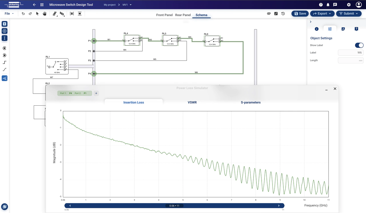
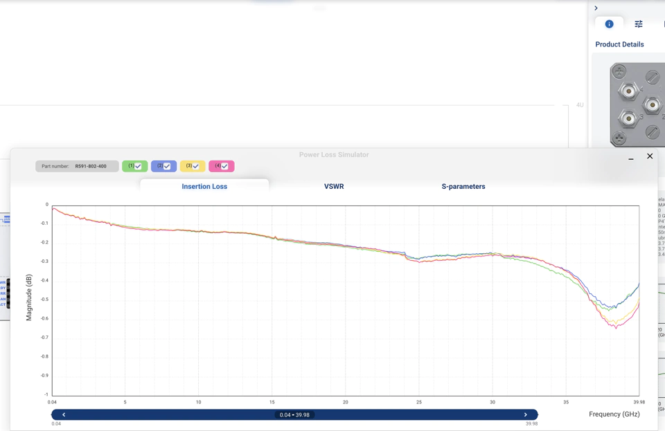
Simulation
MSDT also contain simulator of various power loss characteristics.
It can simulate:
- Insertion Loss - the ratio between input power and transmitted power
- VSWR – the ratio of the maximum voltage to the minimum voltage in standing wave pattern
- S-parameters – scattering parameters between ports
To view the simulated characteristics, launch the simulator through this button
query_stats
and then follow the on-screen instructions
(select the first port and then select the second port or alternatively, it is also possible to select a path between ports).
Now a panel with the simulated characteristic between the two selected ports should open.
It is also possible to add additional paths to compare multiple characteristics (up to 3 different paths).
Just click
add
button and then again select 2 ports or a path between them.
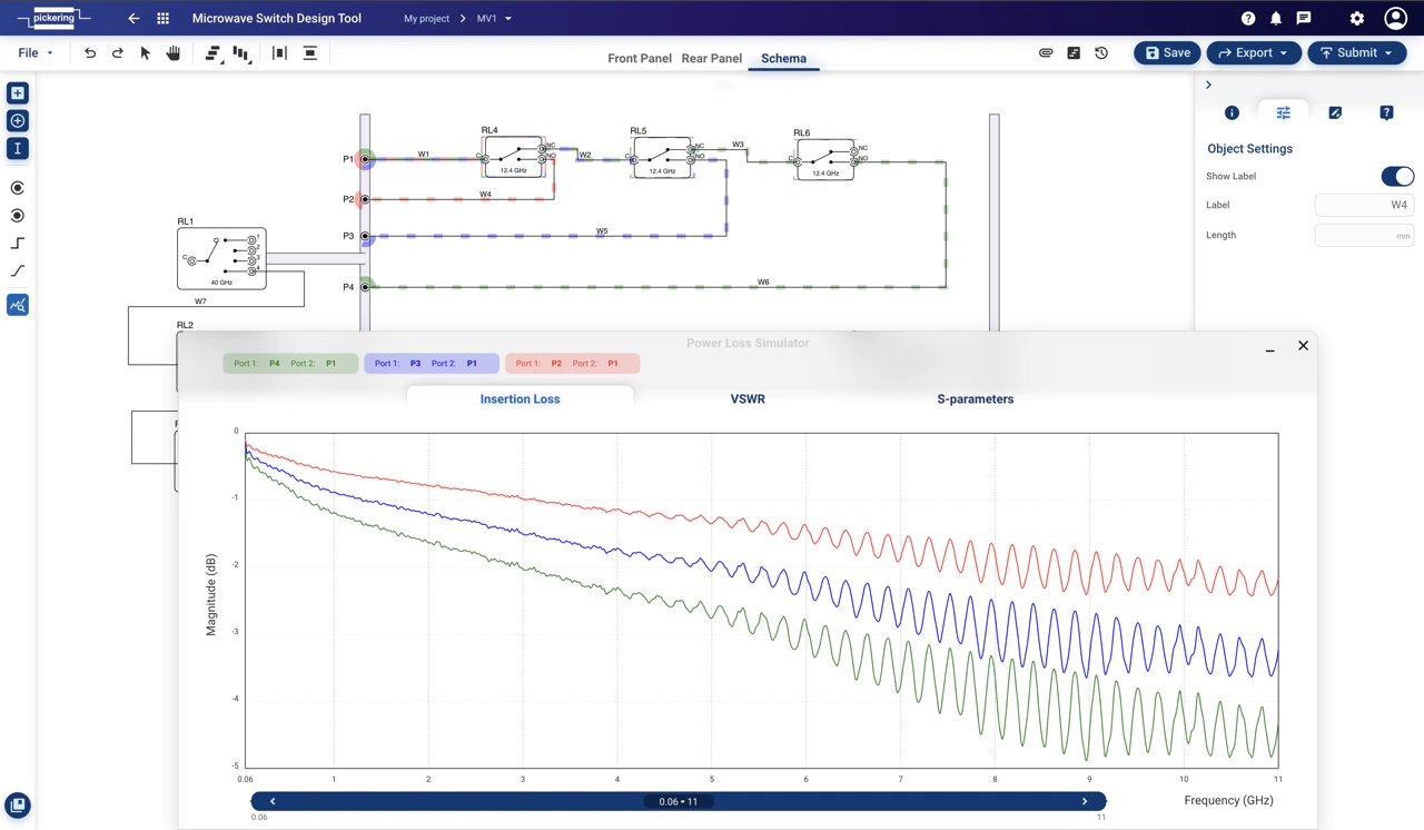
You can also change the displayed frequency spectrum using the slider below the graph.
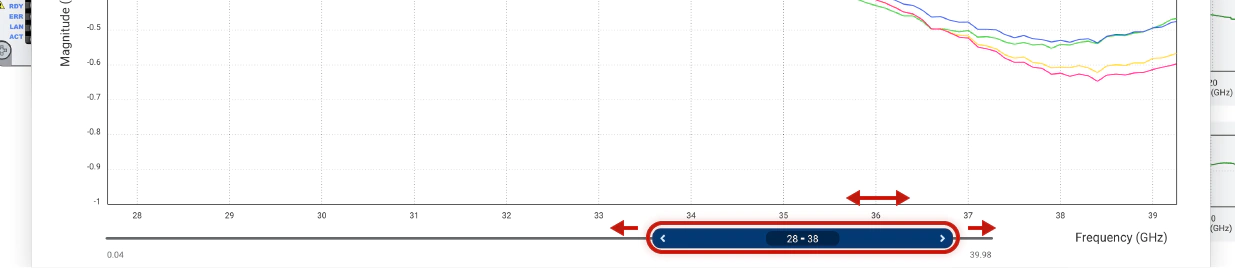
It is also possible to display the port-to-port characteristics for individual relays:
- click on the desired relay (it doesn't matter if you are on the Schema page, Front Panel or Rear Panel)
- in the right panel on the
Product Details
tab you will see previews of the given simulated characteristics.
Hover over one of the characteristics and click the "Show This Plot" button open_in_new
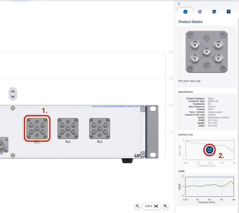
In the picture below you can see the possible result.
You can show and hide individual characteristics using the checkboxes
check_box
System Configuration Tool (WiP)
Purpose
Select appropriate PXI, PXIe hybrid, and LXI/USB chassis, the necessary switching, simulation, and instrumentation modules, as well as modeled Devices-Under-Test (DUTs), to align with your specific system requirements. The tool enhances your workflow by visualizing the system and enabling seamless integration with the Schematic Design Tool for automated cable creation.
- Add a modular chassis or PXI module to begin (alternatively import Schematic Design via Subsystems tab)
- Place modules into chassis slots
- Connect embedded modules to each other to create a subsystem
- Connect the individual pins of your modules within the subsystem using Schematic Design
- Submit your completed design to Pickering
Layout
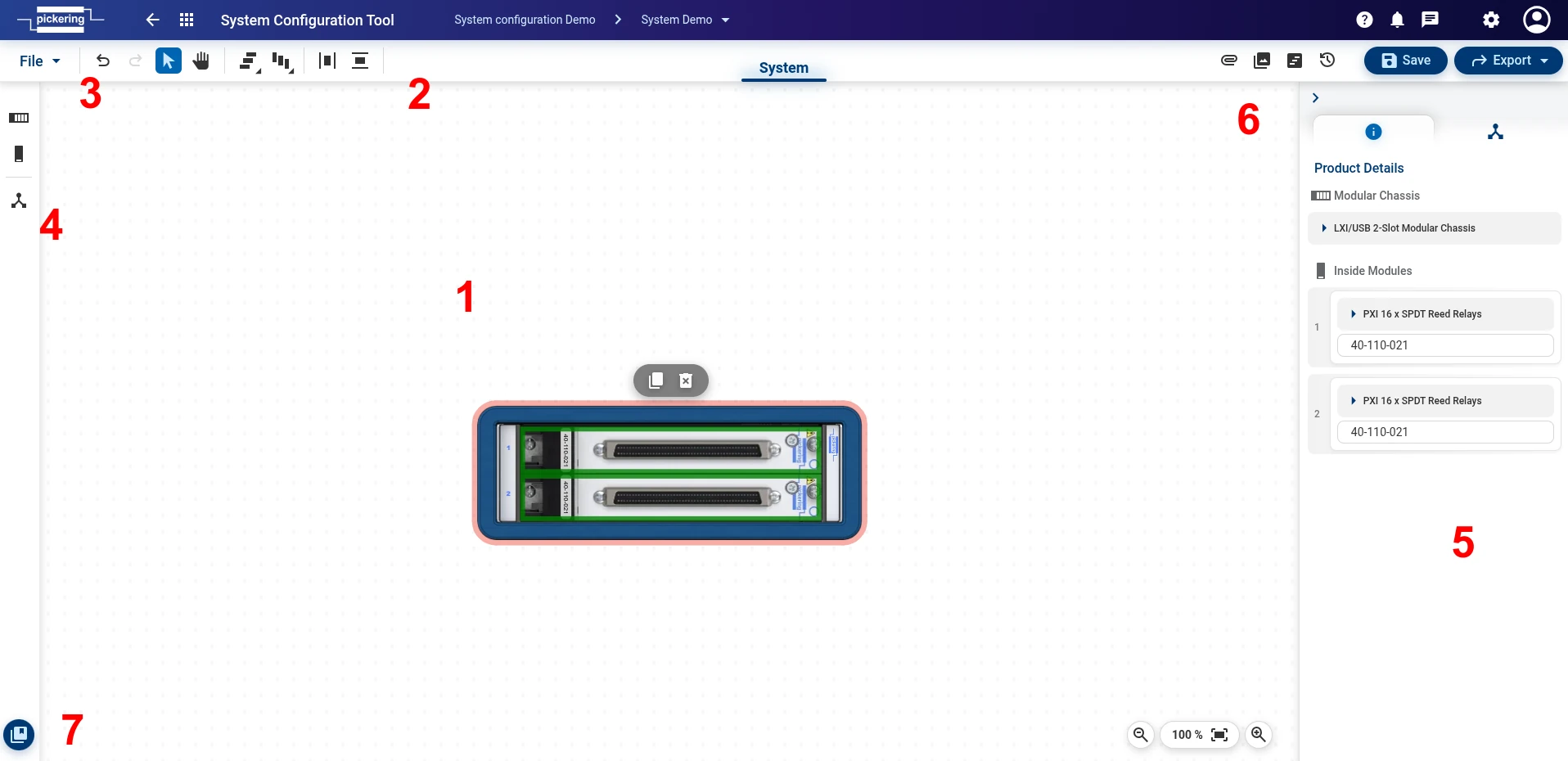
- Drawing canvas
- Tool menu – align and distribute tools, undo/redo
- File menu - contains essential functions to control the file/design. Such as saving, exporting, closing, etc.
- Component menu – add chassis, add module, subsystems
- Right Panel – product detail tab and others
- Attachments, Screenshots, Revisions, History
- Library – component library and custom product
Tool Menu
Tool menu provides functions such as object align and distribute, undo/redo and other

Component Menu
Allows you to add a chassis, a module and create a subsystem
File Menu
File menu provides access to following functions:
- New- creates new, unnamed design canvas. You must use Save As to name and save the file.
- Clear canvas - deletes all active content from the drawing canvas.
- Discard changes- returns drawing to last saved state
- Save - saves the current design.
-
Save As
- allows following options:
- New design – the usual saving of the design, for example, under a different name or to another project.
- New Template – this will save your design as a template that you can load into another design via "Library" button. (note: templates themselves cannot be shared or submitted)
- Import - will import previously saved/exported design datafile, typically with extension *.ssa
- Export - enables to export following types: Data File, SVG file, PNG file, PDF description
- Close - closes design page
Additional Platform Features

Attachments
Attachment function is platform function allowing document storage against design. Please refer to Common Platform Features section for more details.
Screenshots
This function takes a screenshot of highlighted area of drawing canvas.
Right panel will appear. Hit Photo button and highlight preferred area on drawing canvas. On mouse release screenshot will be saved and its thumbnail will appear in the list.
Revisions & History
Revision and history is platform function allowing design history and revision tracking. Please refer to Common Platform Features section for more details.
Export/Import
Export/Import function is platform function allowing exporting design in various formats and importing back into TSA. Please refer to Common Platform Features section for more details.
Messages
Messages are platform functions. Please refer to Common Platform Features section for more details.
Notification
Helps you keep track of the latest system and project changes.
Help
Provides direct access to our comprehensive knowledge base.
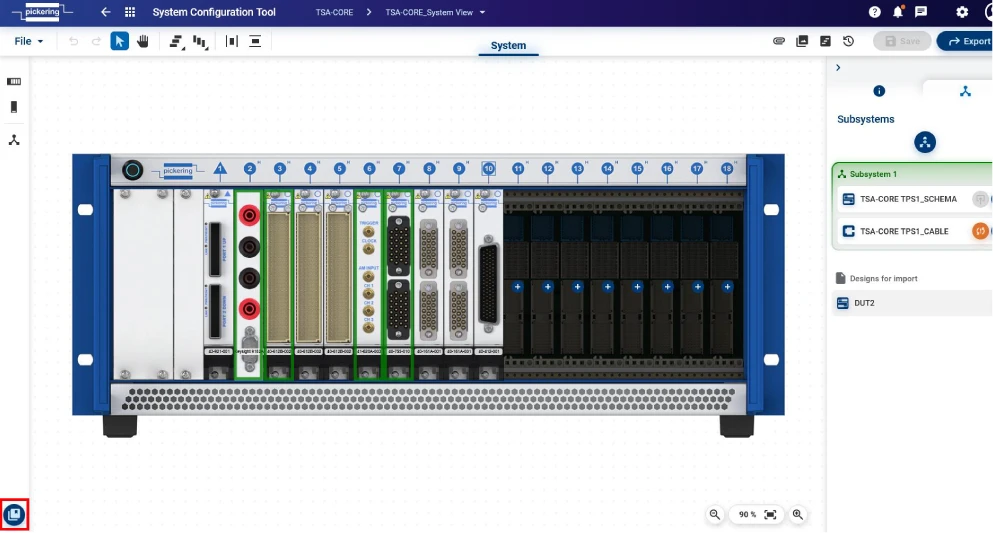
How to create a System configuration
Once you are in the Project Manager Window and have created a project, you can create a System configuration by clicking on the blue highlighted System Configuration Tool button.
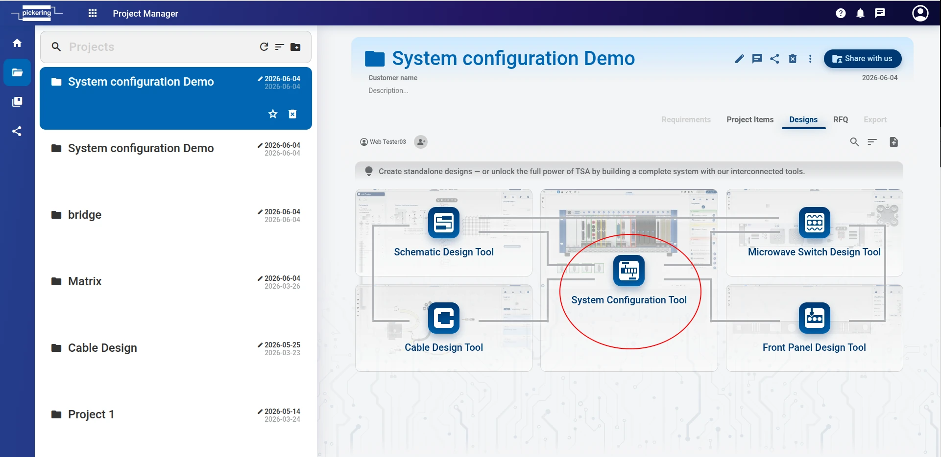
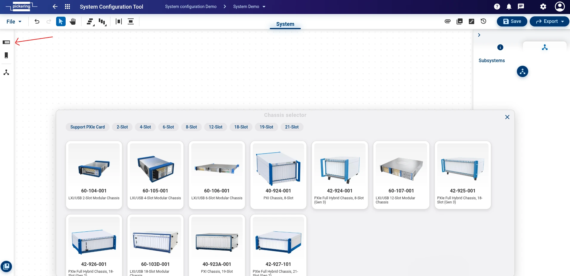
How to use a System configuration Tool
Once you are in system configuration tool, you can start by adding a chassis from the left panel. The chassis selector will appear, allowing you to filter by your required slot configuration or chassis environment (PXI, PXIe, or LXI/USB).
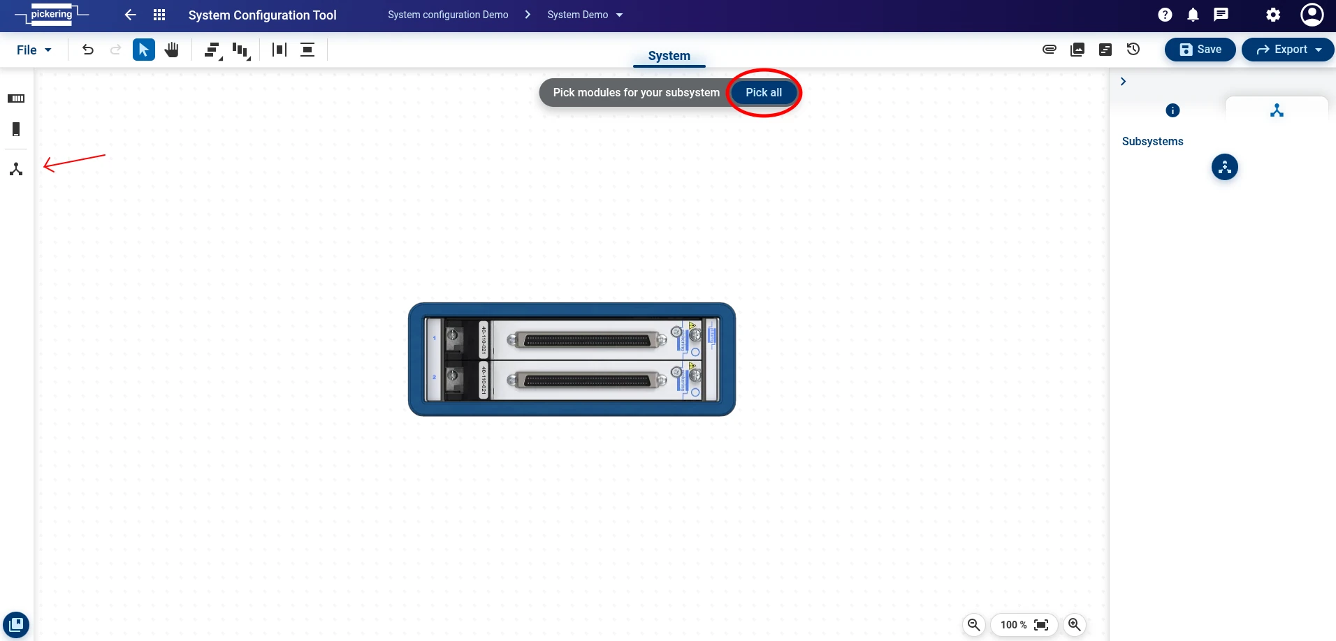
To add modules, click the + button directly on an empty chassis slot
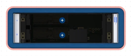
or select Add module from the left panel.
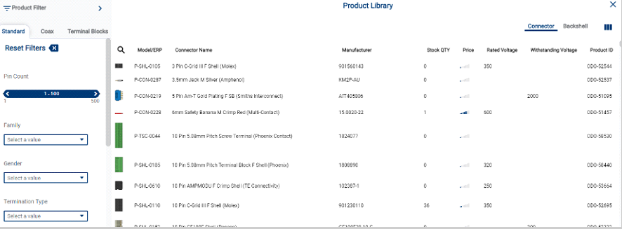
Either way, the Product library will appear so you can choose the desired module. You can search for a product by its product code, description etc., or use the filtering options on the left side of the product library panel.
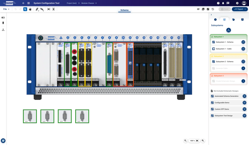
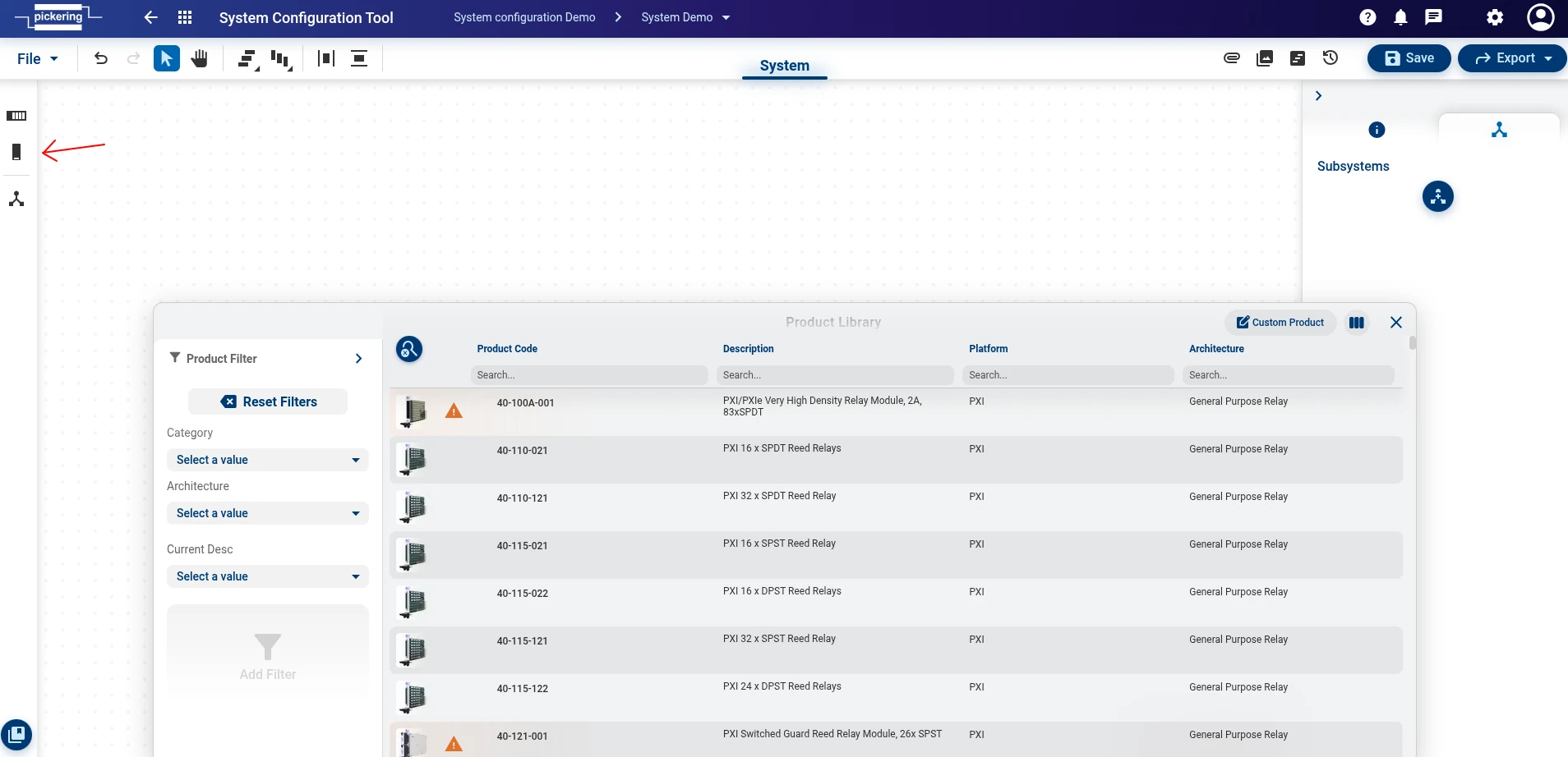
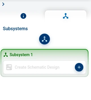
Once all desired modules are added, you can create a subsystem. This can be done again by using the left panel
or alternatively by clicking the Subsystem button on the right panel.
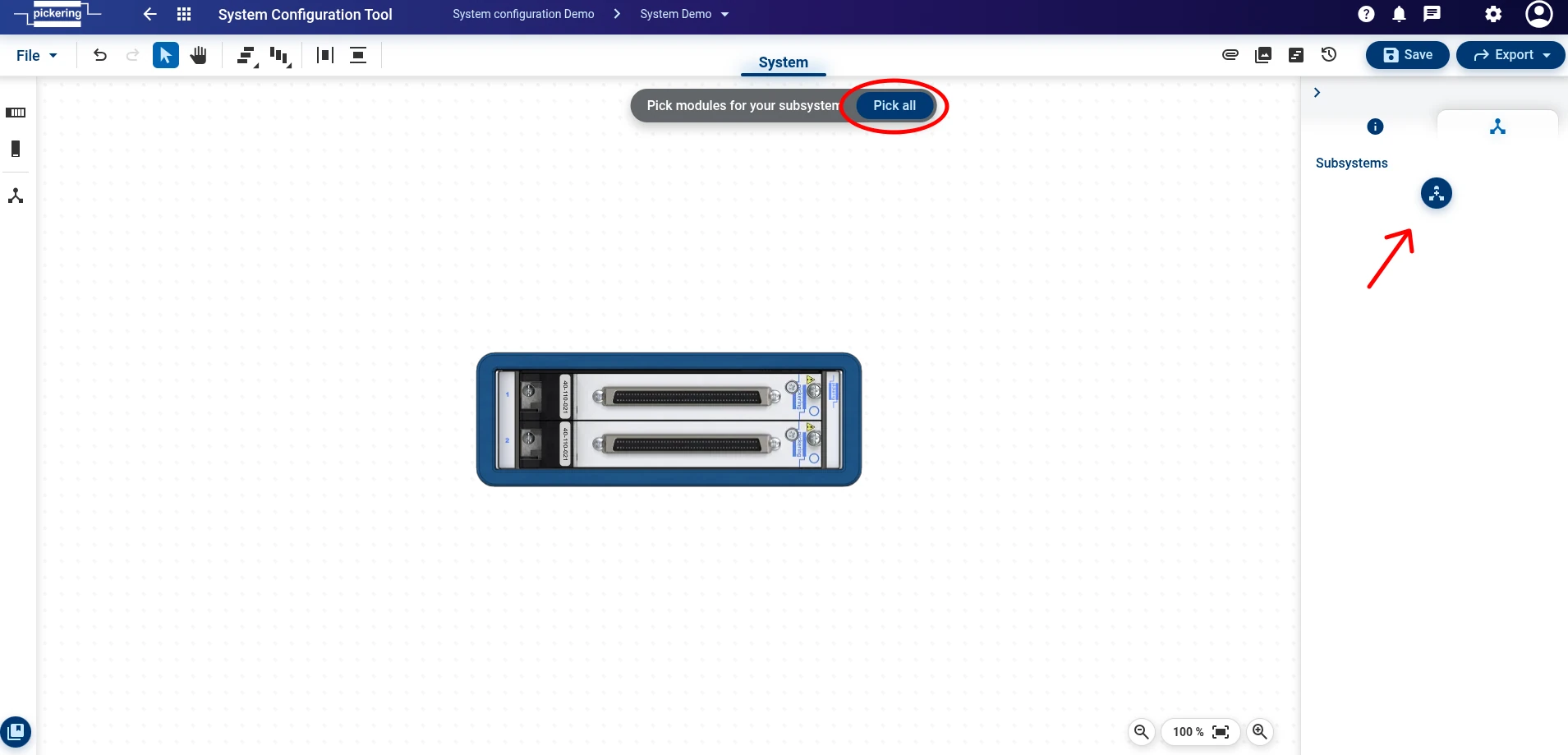
Pick modules for you subsystem by clicking the Pick All button. The subsystem window will appear in the right panel, where clicking the + button allows you to create a schematic design.
A new window with Schematic Design Tool will open. You can create a schematic design by referring to a Schematic Design Tool section.
Once you have completed your design, you can save it and return to the System configuration tool. If you made significant changes to your Schematic design (such as adding a new product or module), you can apply the changes in System Configuration by clicking the orange Update System button in the top navigation row.

Alternatively, you can return to System configuration and hit the orange button Import changes on the right panel.
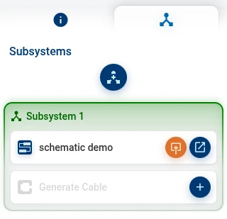
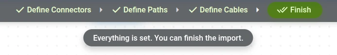
Then, you can generate a cable design by clicking the + button in the subsystem window on the right panel. A new window with Cable Design Tool will open. You can create a cable design by following the instruction at the top of the screen. (Define Connectors → Define Paths → Define Cables → Finish) or by referring to the Cable Design Tool section.
Note that this step is optional — you can skip it and continue without a cable design, or recreate it at any time if you are not happy with the result. You can recreate a cable design by clicking the orange Recreate button at your subsystem.
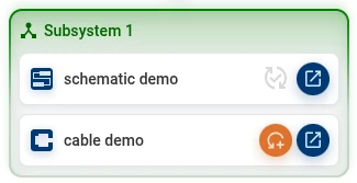
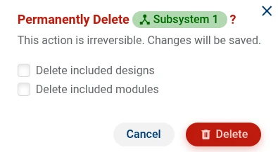
You can create multiple subsystems within your project. If you need to remove one, use the right-hand panel to delete it. When deleting a subsystem, you will have the option to either keep its designs and modules or delete the entire subsystem completely.
Submit to Pickering Workflow
Once you are happy with your design, you can submit your completed Schematic design and Cable design directly to Pickering. As logged in user you have an option to submit design to Pickering for any further assistance, approval or RFQ. To start the process, do the following steps:
- Save the design to your project using button Save as or Save.
- Click the Submit button. Submit form will open.
- Fill in the necessary information and then click Continue
- the Submission Summary window appears, where you can check the entered data one last time.
When you are ready, you can submit your design using the Save & Submit button.
Schematic Design Tool
Purpose
Quickly create detailed hierarchical signal schematics for automated test systems and sub-systems, seamlessly introducing any Pickering switching, simulation and instrumentation modules. Incorporate 3rd-party instruments and Devices Under Test, graphically add all required interconnections and enable automated cable design for streamlined workflow execution.
Creating Schema
The Schema is the most important element in your Test System design phase. All bits and pieces are connected there and from there System Configuration or a Cable can easily be derived.
A Schema Design can be generated either on its own or by creating a Subsystem (a set of cards, DUTs and Instrumentation which builds a group):
Creating Schema without a System Configuration
When you are in the Project Window and have created a project, you can create a Schema by clicking on the blue highlighted “New Schematic Design” Button.
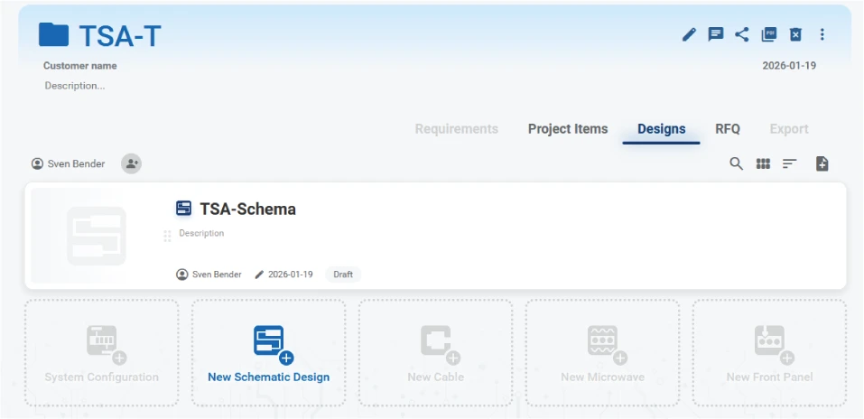
Creating Schema with a System Configuration
If you have created a System configuration you have to create a Subsystem which incorporates all modules, DUTs and Measurement Devices which should occur in the Schema.
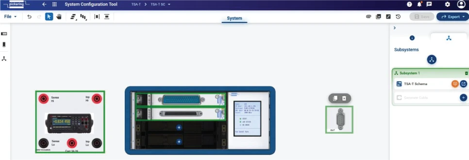
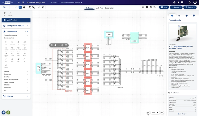
How to use the Schema Design Tool
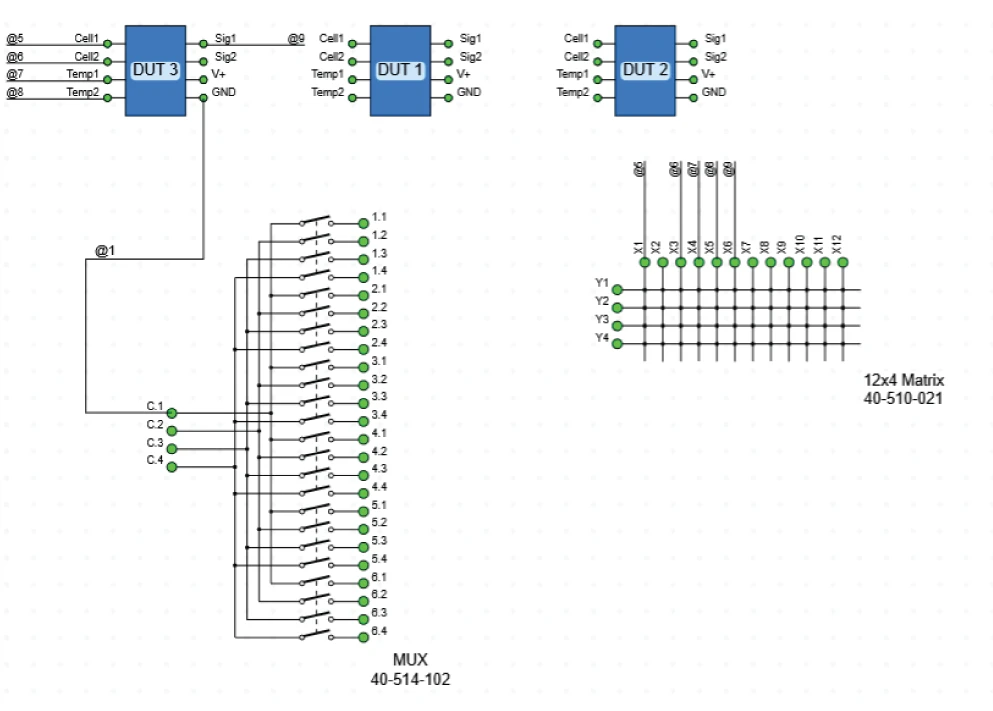
We start with the shown Configuration from Image above. If you now click on the blue button right from the entry “TSA-T Schema” in the Subsystem section, a new window will open and show this view:
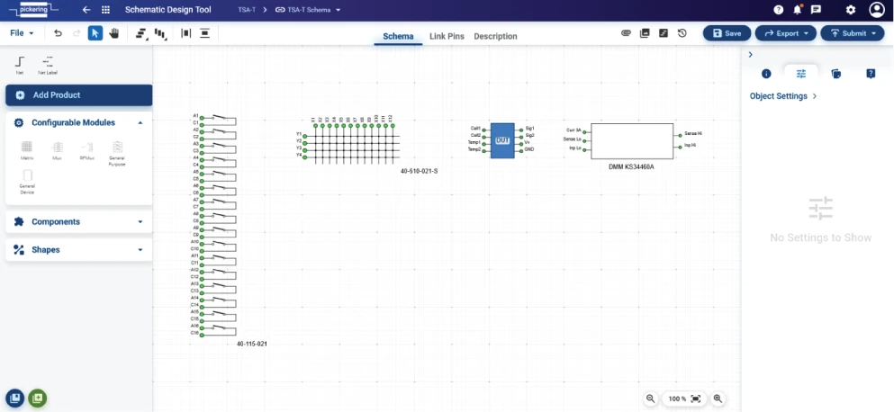
The main window shown in the image above shows in schematic view the elements of your test system. In this case the DUT (blue rectangle), the needed DMM, a matrix card and a relay card.
On the left side in above image you see the pane where you can add elements: Products, Configurable Modules, Components and Shapes:
- Add Products lets you select Pickering Products for your Test System
- With Configurable Modules you can add general devices you use in your schema. These devices do not have any information specific to a physical device (no connection or Pin information).
- Components are electrical components, devices, instruments, which you need to create a circuitry…also these contains no further information how they physically interconnect.
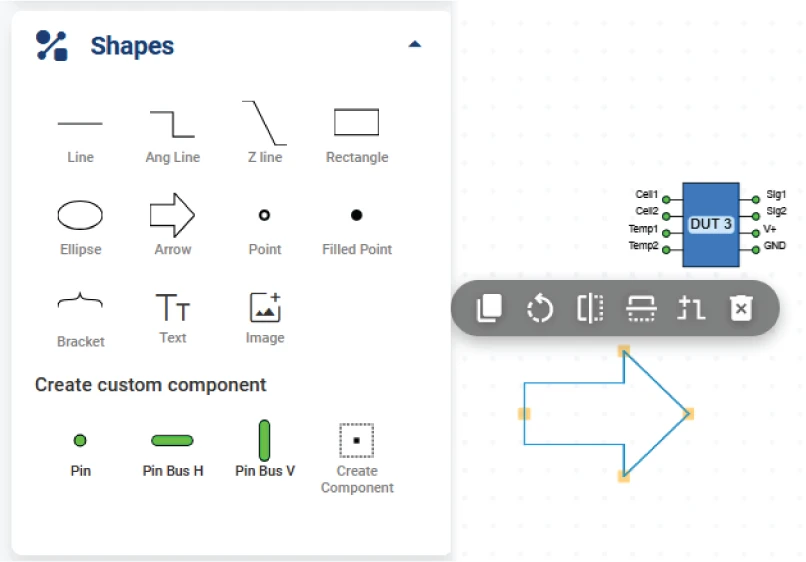
- Shapes
If you plan to create a cable design later, make sure that all schema elements have their physical connections defined. To connect to an instrument, it must have the correct interface connectors and pin-out configured. You can define custom instruments in the Custom Products window — refer to the Project Library / Project Items & Custom Products section for guidance.
Adding Products
You can add additional elements in different ways:
Click on the Add product button in the upper left corner. The Product Library (see also chapter Project Library) window will appear showing the Pickering Products.
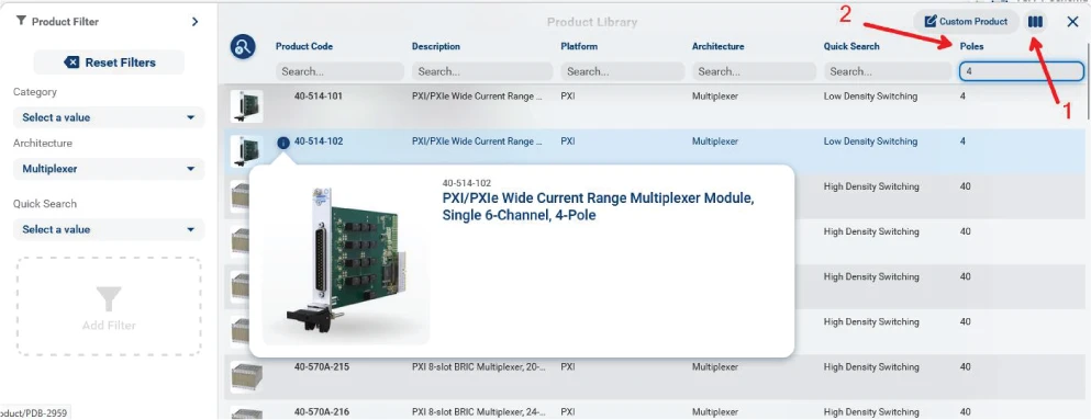
After selecting the desired product it will show up in the schema.
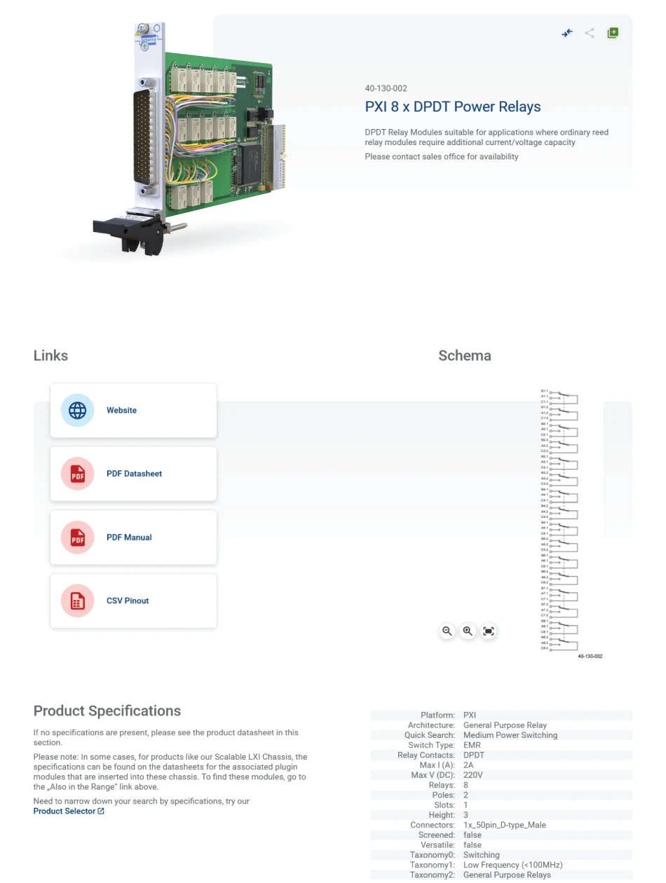
If you click on the blue I-Symbol you will get further information on the selected module in a new browser tab.
See also Chapter Project Library / Project Items & Custom Products for using preselected products you use in your projects.
If you click on the product it will appear in the Schema Design.
Adding Configurable Modules
Please see Chapter "Custom Product Creator" where configurable modules is explained as a part of explaining the Project Library. The functionality is the same if you access it directly via the Schema Design Tool.
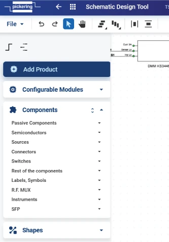
Adding Components
Components are generic elements which you need to complete your Schema. In the image below we added a generic RF-MUX:
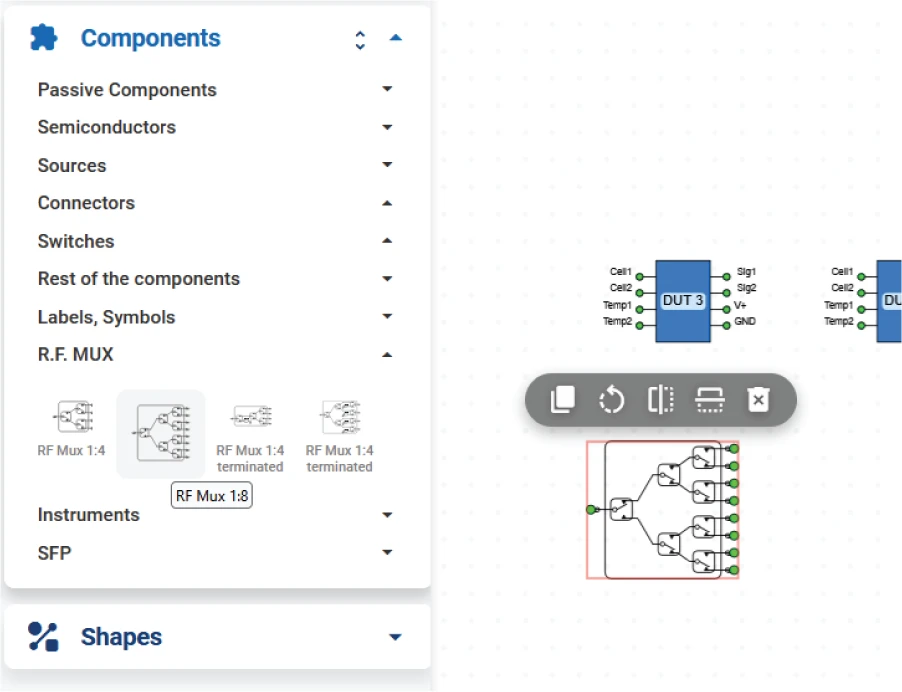 Please be aware that these generic elements do not contain any information about connector or Pin-outs. So it is not recommended to use
them for later cable connections. If you need them as part of a cable connection define them as a custom product in the Project Library
See chapter 2 Project Library.
Please be aware that these generic elements do not contain any information about connector or Pin-outs. So it is not recommended to use
them for later cable connections. If you need them as part of a cable connection define them as a custom product in the Project Library
See chapter 2 Project Library.
Adding Shapes
Shapes are graphical elements to enhance understanding of your Schema. Here we added an arrow:
Linking Elements
After you have all elements in your Schema you have to link the elements. There are 3 ways to link:
- Net tool
- Net Label tool
- Link Pins screen

Net

This is drawing direct connections between the elements. Can make the whole Schema quite busy.
Net Label
This is numbering the connection points. Easy for connecting larger schemas but more difficult to find the according endpoint
Link Pins
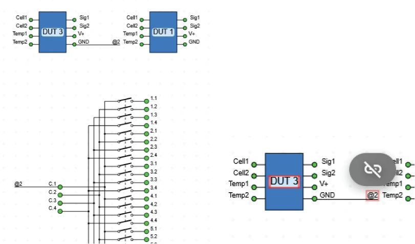
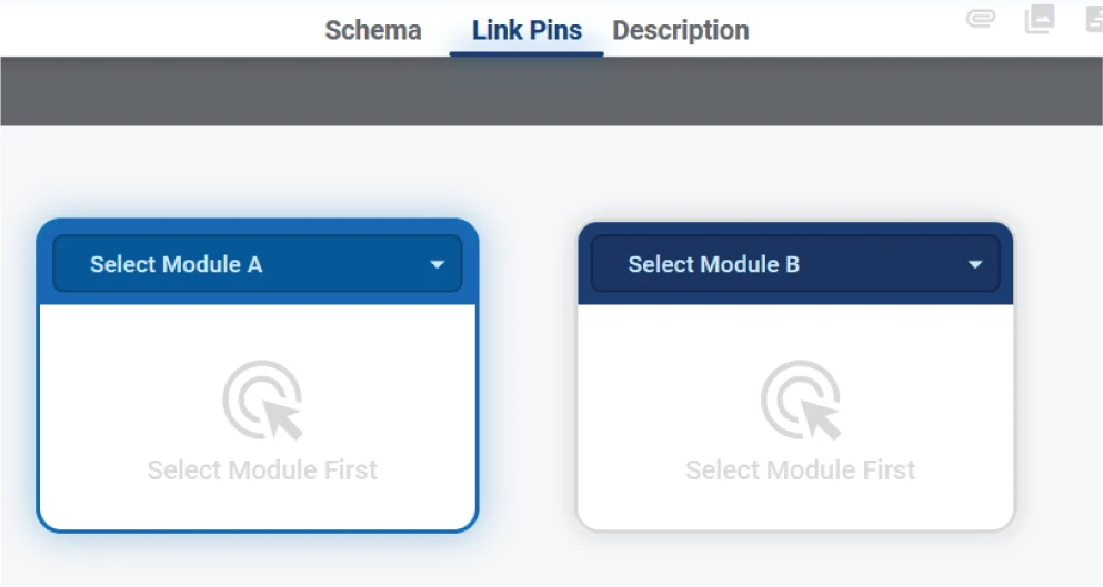
Clicking on the Link Pins Tab shows this:
In below Image the DUT3 and the 12x4 Module were selected to link the appropriate Pins

Pressing “Confirm” in the Autolink Section links the green selected Pins and shows them orange:

If you want to unlink connection(s), press the
After having these modules connected, choose confirm to apply that to the Schema. The Schema should now show the connections:
Front Panel Design Tool (WiP)
Purpose
Create custom front panels for enclosures, complete with connectors, control elements, displays, mechanical parts, etc. The tool provides a user-friendly interface to design, visualize, and prepare front panels for manufacturing.
- Initialize a design to create the basic panel footprint.
- Add circular holes and rectangular cutouts.
- Define irregular shapes and text markups.
- Define irregular shapes and text markups.
- Save or export the design, and finally submit it to Pickering for review or RFQ.
Layout
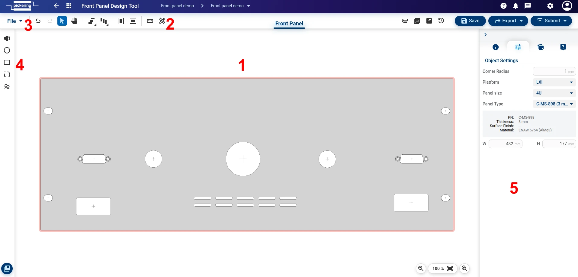
- Drawing Canvas
- Tool Menu - located along the top left; provides object alignment/distribution, undo/redo and two types of ruler.
- File Menu - located at the top left; contains functions to create a new design, clear canvas, save as a new design or save as a template, import data file, export and close design.
- Left Panel - contains tools to add components, circular holes, rectangular cutouts, irregular shapes, and cooling vents.
- Right Panel - tabs contain product details, object settings, notes and queries
File menu functions
- New will create a new unnamed design.
- Clear canvas will delete the entire content of the drawing canvas.
- Save saves the current design state.
- Save as allows the following options:
- New design - standard saving of the design, for example, under a different name or within a different project folder.
- New template - saves your design as a template baseline for use in future designs via the Library. (Note: Templates cannot be directly shared or submitted).
- Import will import a previously saved/exported design data file.
- Export enables you to export the design as: Data File, SVG file, PNG image, or a descriptive PDF summary.
- Close will close the active design page and return you to the project manager.
Additional Platform Features
Attachments
Attachment function is platform function allowing document storage against design. Please refer to Common Platform Features section for more details.
Screenshots
This function takes a screenshot of highlighted area of drawing canvas.
Right panel will appear. Hit Photo button and highlight preferred area on drawing canvas. On mouse release screenshot will be saved and its thumbnail will appear in the list.
Revisions & History
Revision and history is platform function allowing design history and revision tracking. Please refer to Common Platform Features section for more details.
Export/Import
Export/Import function is platform function allowing exporting design in various formats and importing back into TSA. Please refer to Common Platform Features section for more details.
Messages
Messages are platform functions. Please refer to Common Platform Features section for more details.
Notification
Helps you keep track of the latest system and project changes.
Help
Provides direct access to our comprehensive knowledge base.
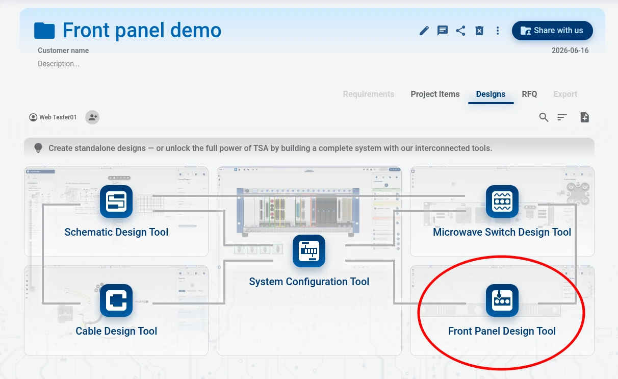
How to create a Front Panel Design
Once you are in the Project Manager Window and have created a project, you can create a front panel design by clicking on the blue highlighted Front Panel Design Tool button.
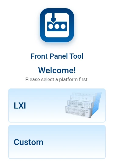
How to use a Front Panel Design Tool
Once you open the Front Panel Design Tool, you will be asked to select your starting platform. You can create a custom panel or LXI panel.
If you select LXI panel you will be asked to select desired size.
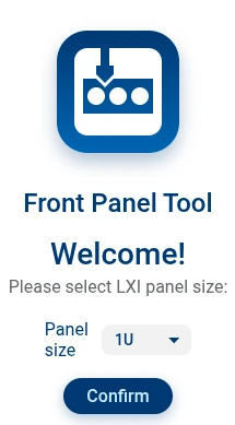
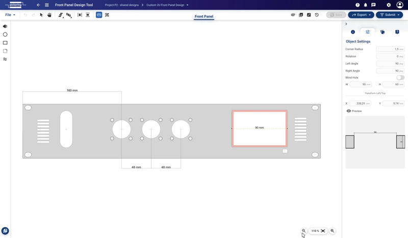
The selected baseline size of the panel will appear on the canvas. You can change the selected platform of adjust dimensions later in the right panel under Object Settings tab.
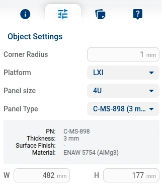
Use the creation tools found in the left panel to create your front panel. Select a component you would like to add, by selecting add component button and clicking anywhere on canvas. The product library will appear, allowing you to search for and select connectors, coax connectors, diodes, control elements, mechanical parts, or fuses.
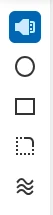
Use the Circle tool to place round cutouts, such as mounting screw holes or circular connector interfaces. Choose the Rectangle tool to create rectangular cutouts for items like screens, displays, or block connectors. Place these elements in your required locations on the panel. Use the D-Shape tool for non-standard cutout profiles that cannot be made with simple shapes. To manage panel cooling, use the wavy Cooling vents tool to add ventilation sloths to your panel.
You can adjust any of selected objects in right panel under Object Settings.
You can submit your completed Front panel design to Pickering.
Submit to Pickering Workflow
As logged in user you have an option to submit design to Pickering for any further assistance, approval or RFQ.
To start the process, do the following steps:
- Save the design to your project using button Save as or Save.
- Click on Submit. Submit form will open.
- Fill in the necessary information and then click Continue
- finally, the Submission Summary window appears, where you can check the entered data one last time.
When you are sure, you can submit your design using the Save & Submit button.
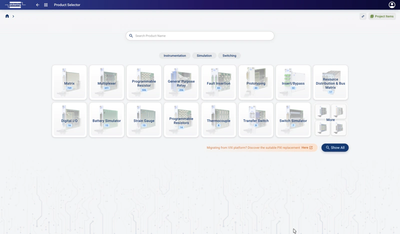
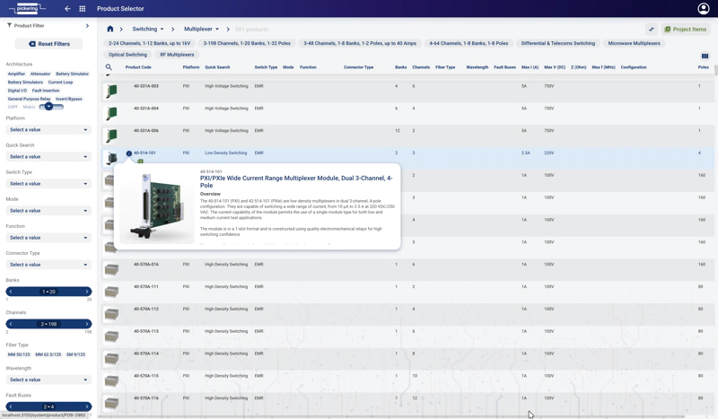
Product Selector
Purpose
Access the comprehensive database via specification filters, enabling you to quickly select the required products to incorporate into the Schematic Design and System Configuration Tools.
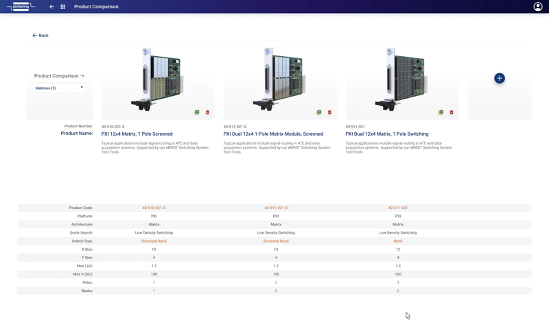
Product Comparison
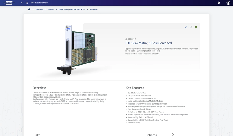
Product Info View
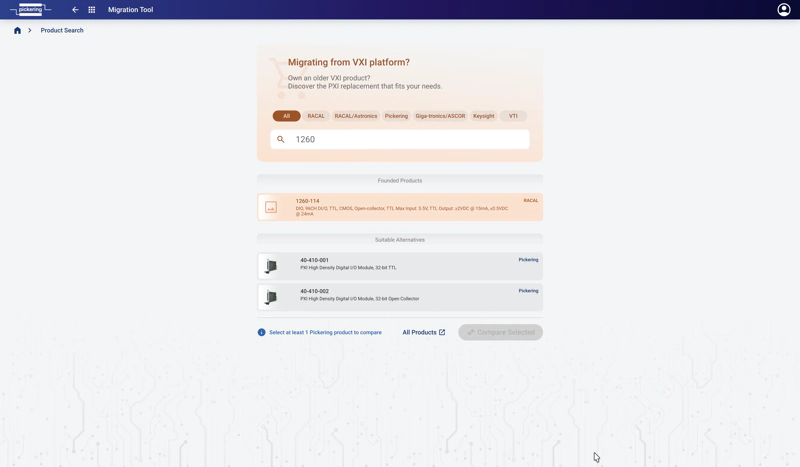
Migration Tool (WiP)
Simplifies the transition from legacy test systems such as VXI and GBIB to fully-supported PXI architectures. The tool lists a comprehensive selection of obsolete products and suggests functionally compatible Pickering PXI modules.
Project Library / Project Items / Custom Products
This section explains definition & creation of Project Items & Custom Products.
Very often you use your favourite pre-selected modules and test equipment in your projects. To have easier access to preferred modules there is the option to define them as Project Items.
Custom Products can represent T&M equipment, DUT or auxiliary HW you are using in your test setup. Both elements are stored in the Project Library to have an easy access.
My Library
The Project Library is represented by this Icon and is visible in the System Configuration Window at the lower left corner:
If you click on this Icon this window will occur:
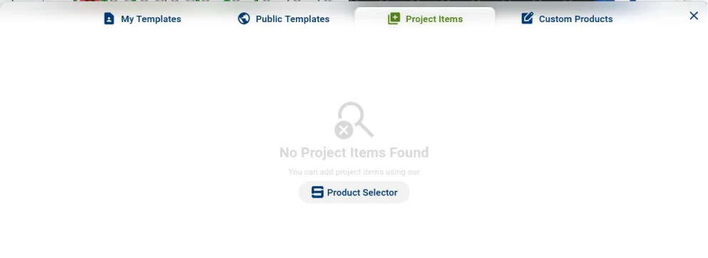
Project Items
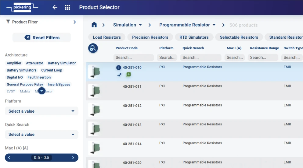
Clicking on Product Selector in Image above will open a new window where you can choose the right product for your project:

By selecting the categories or searching for product you can get to your needed product which then shows up like this:

You can now add the product to the Project Items List by clicking on the upper right green icon.
Alternative Possibility to add Project Items
You can also use the Project Items Tab in the Project Manager window. If you click on a project, you see this:

If you click on the Project Items this Tab shows up:

In this Tab you can get more information by clicking on the blue button or delete the product (bin symbol).
To add new modules press the “Product Selector” Button. A new Browser Tab pops up, in which you can select products and add it via the green Symbol to the Project Items List:

Clicking on the green “+” Symbol adds the module to the Project Items List. You may also open the Product Information (blue “i”-Circle), there is also the green “+” Button.
In Product Selector you have several options to filter products for easier selection. On the top right you find the "Add Column" symbol:

which lets you add additional filters for selecting the best module for your purposes.
Just ot remember: The modules you have selected are showing up in the System Configuration Windows, when pressing the library button
Custom Product Creator
If you design a test system there are lots of components not available as standard in TSA, i.e. T&M equipment, specific HW, or the DUTs you are using. To create a representation of these elements you can define a Custom Product in My Library
After clicking on the last tab, you see this window:

When pressing the Create New Button a new browser window (Custom Product Creator) will show a subset of the Schema Design Tool to define your custom device:
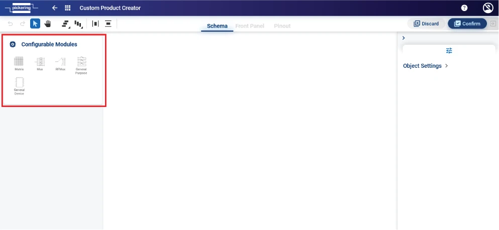
In the Configurable Modules Section you select the module you want to create. In general a self defined element for your Schema consists of 3 Elements: Schema, Front Panel, Pinout.
While the Schema represents the internal wiring and connections used for the Schema Design Tool, the Front Panel defines the connector of the element. To connect then Schema and Front Panel you need to define the Pinout.
Let’s show an example.
Example: Creating a 10 Pin DUT
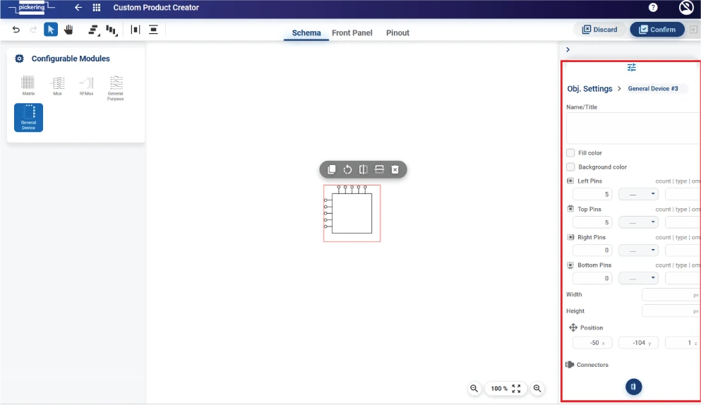
In Object Settings you can define several options of the device you want to create, i.e. which pins should reside where.
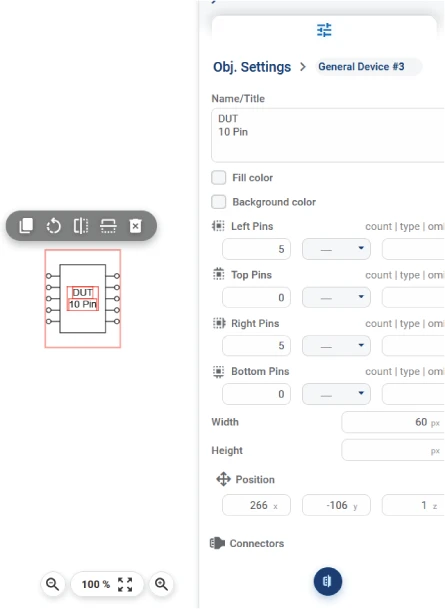
Here we have created a 10 PIN DUT. 5 Pins on the left, 5 on the right side of the rectangle.
You can name the DUT in the Name/Title Field
Fill Color & Background Colour can be defined
The Pin count can be defined for the for sides of the rectangle and you can also define the type the connection and if Pins should be omitted in the graphics.
Width & Height can be defined
To define a connector, you can either do it here where you can select from nearly every connector available or you can use later the Front Panel.
Let’s use the Front Panel in this case.
10-Pin DUT Front Panel
Click on the Front Panel Tab.
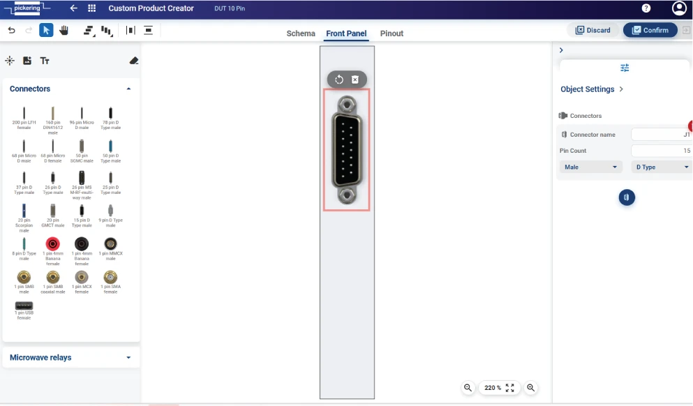
In the image above a 15 Pin D-Type from the connectors section on the left was selected and added to the Front Panel. You can rename the Connector name and adjust the Pincount.
If you click on the grey area (which is the physical front plate) you see which properties this has. In our case a 1 Slot PXI was selected:
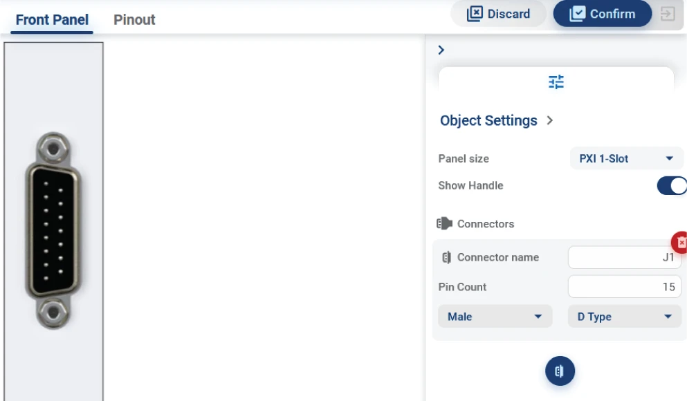
In the field Panel Size you can also choose other formats, amongst them Custom Sizes, too.
10-Pin DUT Pinout
After defining Schema and the Front Panel we have to connect the logical schema pins with the physical pins of the connector. This is necessary if you want to create a cable later.

You can now connect the Custom Product’s pins with the connector pins. The TSA pin alias’ are showing up when you use the Custom Product in you schema.
Press Confirm Button on the upper right of the screen and you have created your DUT:

Submission Process
Introduction
The submission process is a procedure that allows you to easily get your design to a final manufactured product or quotation.
With expert assistance from Pickering, you'll be sure that your design will be completely fine.
Cable Design Tool – Design and Manufacturing Termsopen_in_newSchematic diagram of the process

Individual steps
As logged in user you have an option to submit design to Pickering for any further assistance, approval or RFQ.
(Individual steps may vary slightly depending on the used design tool.)
Once you're satisfied with your design you can start the process following these steps:
- Save the design to your project using button Save as or Save.
- Click on Submit. Submit form will open.
- Fill in the necessary information and then press Continue
- finally, the
Submission Summary
window appears, where you can check the entered data one last time.
When you are sure, you can submit your design using the Save & Submit button.
After that, the following happens:
The status of your design will change to
Submitted
and then Pickering will review your design and get back to you.
Keyboard Shortcuts
infoFor Apple devices, keep in mind that some keys are different: Ctrl = command, Alt = optionDesign Tools keyboard shortcuts
Design Interactions
Canvas Interactions
Object Interactions
Tool Operations
Selection
Miscellaneous
FAQ
Solution:
Shared Projects: You can see shared projects in the Project Manager (app menu) in the Projects section (left panel).
Shared Design: You can find designs shared with you in the Collaboration section (left panel in the Project Manager).
lightbulb Tip: Check if the account You are logged in with matches the email address to which the project/design is shared.Solution:
Creating a cable design as part of a subsystem is optional. You can skip it and continue without one, or recreate it at any time if you're not happy with the result — there's no need to delete it.
Solution:
First, check if the email the design/project was shared to matches your TSA login.
If the previous solution doesn't work, try asking the design/project owner to reshare it.
1nd Possible Reason (locked design)
Check if there is a red lock in the header next to the design name.
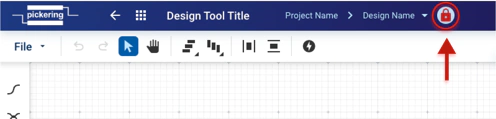
If so, it means the design is open elsewhere and cannot be edited/saved.
lightbulb Tip: You can see why the design is locked by hovering over the red lock or checking the popup after refreshing the page.2nd Possible Reason (connection issues)
infoIt seems the TSA server is unavailable, or there may be an issue with your internet connectionWorkaround:
Export the design data file using the File > Export > Data File option in the upper-left dropdown menu, or by clicking the "Export" button in the upper-right corner.
Solution:
- In the Project Manager, find the desired project and then press the "Sharing" button (in the upper right corner or above the designs next to your username).
- Press "Share" and then enter the email of the person you want to share the project with and set its permissions.
- Confirm by pressing "Share"
Solution:
Save the desired design as your template. File > Save As > New Template. Access it any time - go to Project Manager, select 'My templates' and pick the design you previously saved. Use it in any of your future projects.
Solution:
Locate the design in the specified project within the Project Manager. Then, drag and drop the design you want to move into the desired project.
Solution:
Open the desired design, then select File > Save As > New Design from the upper-left dropdown menu. Enter the required information and click "Save".
Solution:
Open the desired design, then select File > Import. Do the same for export. File > Export and choose the preferable format. (Data File, SVG, PNG...)

